INA199: INA199A1DCKR

Part Number: INA199

Tool/software:

We are struggling with the INA199A1DCKR.


We are using the IC to measure the current coming from a DCDC converter (0V up to 19V) through a 0R025 resistor, see the following picture:


Additionally the output OUT2.10 can be switched ON and OFF with the MOSFET V1101.


We are getting devices back from the field due to broken resistors (10 Ohm) and sometimes also 24V Z-Diodes (22.8V@5mA).

Could you give us an hint how we could improve our circuit to manage surge pulse (ideally 2kV with 40 Ohm in serie) coming from OUT2.10?

We suppose that one weak point is varistor R1129 (Vclamping 67V), otherwise we cannot see other improvements.

  • Sara,

    I would check out this reference design for help with dialing this in. 

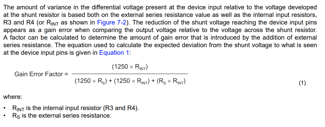
    Transient protection for our devices is challenging when they are large in magnitude. You can increase the resistors to throttle the current, but this comes with the tradeoff that you must balance these resistors with the amount of error they will inject into the circuit:

    One thing I am noticing here is that it looks like the customer is using this device where there are multiple grounds. I cannot see which GND the device is referenced to via their schematic, but the REF and output are referenced to a different ground than than the measurement line. This is typically not advisable for these types of parts, as abs max values in the datasheets will be based off of the values of the referenced GND. If they are getting significant GND bounce in the circuit, this alone could be causing their failure issues. Can we confirm why they are splitting GNDs on the device?

  • About the GND: yes in the schematic there are 2 different gnds (AGND and GND) but they are connected at one point, so both low impedance path.


    Yes we read about this part of the datasheet, the tradeoff between accuracy and protection. In the meantime we could have found a workaround to increase the surge stability: with Schottky diodes between and the supply, and with increased output capacitor value.

  • Sara,

    Understood on the GNDs. Provided they are tied that should mitigate my comment above somewhat, but just make sure the customer is aware that GND difference can occur between the load line and the part itself. 

    I'm glad you found a workaround here. In case this does not pan out, there is an alternate method the customer can examine to bound the error of the GAIN error equation I list above. That method is introduced in this app note, and detailed in this one