Part Number: TPA3129D2
Tool/software:
Hi I'm quite new to all this.
I'll be referencing the TI Datasheet throughout.
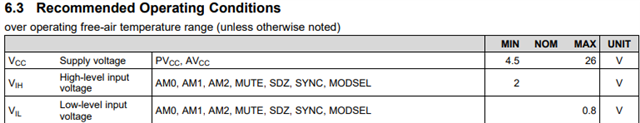
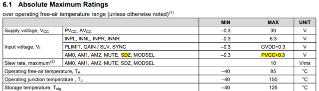
My confusion stems from the wording on the pin description. For the SDZ pin and other logic pins it reads, "TTL logic levels with compliance to AVCC." To me this means I should pull up the pin with avcc. So my first question is how do I connect those 2? Is it simply from the avcc pin?
My second question is about part 7.3.10 Short-Circuit Protection and Automatic Recovery Feature which says I can achieve automatic recovery by directly connecting SDZ and FAULTZ. My question is where should that connection be? And can I similarly pull up FAULTZ with avcc?
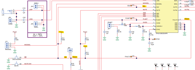
Lastly I got confused over Figure 36. in part 8.2 Typical application. Here the SDZ pin is being pulled up by GVDD. This confused me, despite also the SDZ, FAULTZ and MUTE pins being pulled up by GVDD in Figure 28. Section 7.3.10. The reason this confused me is because in the pin description for GVDD is states that it is "Not to be used as a supply or connected to any component other than a 1 μF X7R ceramic decoupling capacitor and the PLIMIT and GAIN/SLV resistor dividers." So I'm wondering why it is used that way in the datasheet schematics. And if I can't use GVDD, how do I connect AVCC to my logic pins to pull them up high?
bonus question! Can i just tie MUTE to ground if I never intend to add a mute function?
Thanks for reading all that.