This thread has been locked.

If you have a related question, please click the "Ask a related question" button in the top right corner. The newly created question will be automatically linked to this question.

INA851: INA851

Part Number: INA851


Tool/software:

Hello TI Team

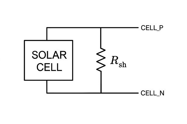
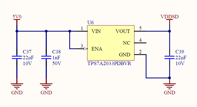
I want to measure as differential the response of a solar cell to irradiance through a shunt resistor using the INA851 instrumental amplifier. I have attached the connection of the solar cell with the shunt resistor and the circuit schematics below. The INA851 supplies are ±5V0. The INA851 differential outputs are read by the STM32F373RBT6 MCU's internal sigma-delta ADC.

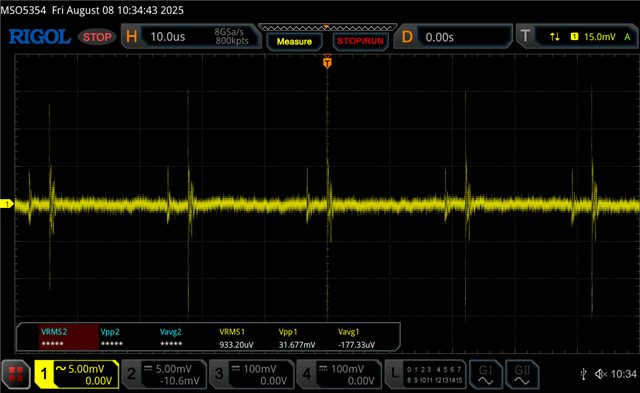
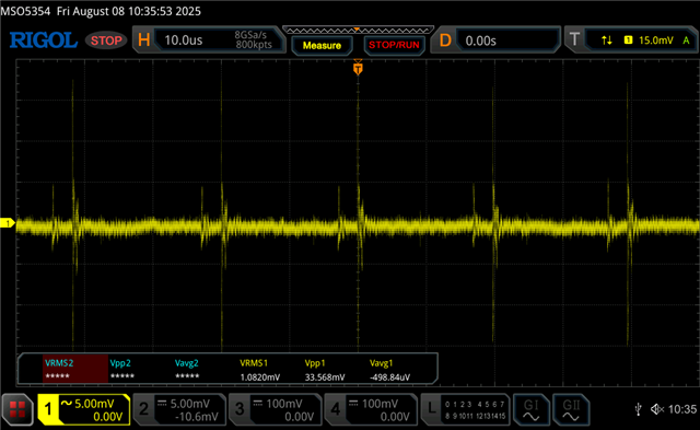
My problem is that I see ripples in the sigma-delta ADC data. There are fewer ripples at low irradiance and many more at high irradiance.

I have tried many variations for the differential and common filters at the INA851 inputs and outputs, but to no avail.

I would be looking forward to your help on how to proceed. Thank you in advance.

  • Hello Bekir,

    I have a couple thoughts to check.

    Have you verified the stability of your MCP607 buffer circuit?Any oscillation on VOCM will couple directly into the output of the INA851. This should be getting canceled out as a common-mode error, but should be ensured to be correct regardless. Here is their recommended RISO values for different capacitive loads, 100 ohms may be too small for 100nF

    Additionally, I notice that your power pad is connected to GND. It should be connected to V- per the datasheet. 

    Do you have an oscilloscope capture of the output ripple? Additionally, what is generating your +/-5V rails?

    Best,
    Gerasimos

  • Hello Gerasimos,

    Could the Thermal Pad being connected to GND cause these ripples?

    I am sending the measurements of the ±5V0 supplies, Vocm output, and ADC inputs for the INA851 with an oscilloscope below.

    VS+ measurement across the C56 capacitor. Oscilloscope probe in AC Coupled mode.

    VS- measurement across the C66 capacitor. Oscilloscope probe in AC Coupled mode.

    VOCM measurement across the C46 capacitor. Oscilloscope probe in AC Coupled mode.

    Measurement of the INA851 outputs across the C61 capacitor by removing the solar cell and shunt resistor from the circuit and shorting the INA851 inputs CELL_P and CELL_N. Oscilloscope probe in DC Coupled mode.

    I have also added a graph of the ADC data.

    Graph of sigma-delta ADC data when low irradiance is applied to the solar cell while the solar cell and shunt resistor are in the circuit.

    Graph of sigma-delta ADC data when low irradiance is applied to the solar cell while the solar cell and shunt resistor are in the circuit.

  • Hi Bekir,

    Gerasimos is out, and I'll be covering for him. 

    Could the Thermal Pad being connected to GND cause these ripples?

    It' possible, however I can't say whether it's the cause or not as we didn't evaluate the device's performance when tying the thermal pad to any voltage potential than VS-. 

    Additionally, what is generating your +/-5V rails?

    Repeating what Gerasimos has asked. The VS+ and VS- rails look very noisy, especially the sawtooth signal from VS-, and I'd like to figure out if this noise is coming from the solar cell or the devices that are generating those supplies. 

    Best Regards,

    Robert Clifton 

  • Hi Robert,

    The noise on the power rails is related to the source devices. 5V0 is generated by the LMR51610XFDBVR buck regulator, and -5V0 is generated by the LM2776DBVR Switched Capacitor Inverter.

    I am also including the output of the solar cell measured across the electronic board below.

    Measurement of the CELL_P solar cell positive output via the electronic board input connector. Oscilloscope probe in AC Coupled mode.

    Measurement of the CELL_N solar cell negative output via the electronic board input connector. Oscilloscope probe in AC Coupled mode.

    Measurement of the CELL1_P INA851 positive input via the C62 capacitor. Oscilloscope probe in AC Coupled mode.

    Measurement of the CELL1_N INA851 negative input across the C59 capacitor. Oscilloscope probe in AC Coupled mode.

  • Hi Bekir,

    Are you able to supply the INA851 with external power supplies that are cleaner to see if that's the cause for the noise you are seeing on the output? 

    Do you see those ripples that are coming from the solar cells that you have shown here? I'm not sure if the filter between the solar cells and the INA851 are filtering it out. 

    Best Regards,

    Robert Clifton