OPA991-Q1: DC-DC switching Noise seen at the output of the circuit

Part Number: OPA991-Q1
Other Parts Discussed in Thread: OPA991, TLV888, OPA827

Hi,

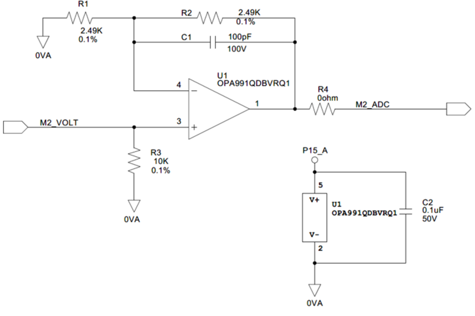
I am using following circuit to amplify the output of a Hall Effect current sensor output before supplying in to and ADC. The input and output waveforms are provided below. The output has 180kHz switching noise eventhough the input doesn't contain it. Both waveforms are captured with respect to same ground point and by using low voltage differential probes. The Circuit Card Assembly has an Isolated flyback converter (Vin=28V, Vout1=15V, Vout2=15V, Vout3=7.5V) operating with switching frequency of 180kHz. The noise at P15_A w.r.t 0VA is shown in the 3rd figure below.

Can you help us understand, how the common mode noise from DC-DC couples into the opamp? Also, Can you suggest a design modificaiton to mitigate the issue?


image.png

OPA991 Input (Red color) and Output (Cyan Color)

image.png


P15_A Noise Measurement with respect to 0VA

image.png


Thanks,

Shihab.

  • Shihab,

    There are a few possibilities for the cause of this issue.

    1. I think the most likely is power supply rejection.  In your waveforms it looks like the 180kHz signal on the power supply is about 24mVpp.  The power supply rejection (PSRR) at this frequency is about 35dB (see below).  35dB of PSRR translates to about 17.8mV/V of rejection.  With a 24mVpp noise on the supply the input referend noise from PSRR is (24mVpp)(17.8mV/V) = 0.427mVpp.  The noise gain of the circuit is 2V/V, so the output noise would be about 0.854mVpp.  I do not see a scale on the output graph so I don't know if this is close to what you are seeing.  Op Amp Offset Voltage and Bias Current Limitations covers PSRR theory.
    2. I noticed the power supply noise does not have the same shape as the output noise.  To some degree that is to be expected as the PSRR will change the shape of the signal.  However, in your case the noise looks like a dampened oscillation.  I suspect that you may have a stability concern that is triggered by the noise from the PSRR.  I see that the op amp is connected to an ADC based on the schematic notes.   Is there a capacitor filter at the input of the ADC?  If not, can you check the input capacitance of the ADC?  When an op amp drives a capacitive load the output can have overshoot and oscillations.  Depending on the op amp characteristics and the size of the capacitance the overshoot and oscillations may not be too bad but enough to magnify the noise from PSRR.  Try removing R4 and measure the op amp output directly.  
    3. You may want to capture the power supply noise and output noise on the same scope waveform.  It would be good to confirm that the output noise aligns with the power supply noise.  There seems to be two sets of oscillations that are closely spaced on the output  I think those may relate to the rise and fall of the noise on the supply.
    4. It is possible that there is some other coupling mechanism between the switching supply and the output signal.
    5. What is the sampling rate of the ADC?  If the ADC is sampling near 200kHz, it is possible that the noise is from the ADC and not the PSRR of the op amp.

    Here are some possible solutions:

    1. Choose an amplifier with much better AC PSRR.  This is pretty challenging to find one that is really good at 180kHz.  TLV888 looks a little better (about 40dB).  OPA827 is better (especially for the positive supply), but the cost is high compared to OPA991.  In any case, you could try a device with better PSRR as an experiment to see if it helps (confirm that the PSRR is the issue).  One thing to remember about the curves is that they are typical, so the actual PSRR could be better or worse than the typical curve (+/-20% on the linear value is a good estimate).  By linear value, I mean the PSRR in mV/V.
    2. Assuming the issue is PSRR the best solution is to reduce the power supply noise.  Alternatively, reducing the frequency of the noise will help because PSRR is better at low frequency.  The most common approach to reducing the noise is to use an LDO with good AC PSRR.  Another approach is too increase decoupling or add a resistor in series with the op amp supply before the decoupling (i.e. low pass filter on the op amp power supply).  A 10 ohm and 1uF decoupling will create a 16kHz low pass filter which should significantly reduce your 180khz power supply noise.  The issue with doing this is now you have a voltage drop on the resistor that will depend on the op amp current consumption.  This is why you should try and limit to 10 ohms or less.  OPA991 doesn't have a high IQ so this may work well.  
    3. If the op amp does have a minor stability problem that is effectively amplifying the noise, you can choose a value for R4 to improve stability.  I can help with selection of the resistor if the op amp does connect to a capacitive load.
    4. If noise is coupling into the op amp through a different path, it could be a PCB layout issue.  The data converter video series has a section covering PCB layout to minimize coupling of noise signal.

    I know that is a lot of info.  I hope it helps.  I think it is a combination of PSRR and stability.

    Best regards, Art