THS4511-SP: Question about stability analysis and simulation model of THS4511-SP and THS4513-SP

Part Number: THS4511-SP
Other Parts Discussed in Thread: THS4511, PSPICE-FOR-TI, TINA-TI,

Hello,

I am considering one of the THS451x-SP FDA and was looking through the datasheet. One thing that surprised me is the 348 Ohm RF value without any feedforward capacitance, considering the input capacitance of the input pins (1.5pF CM, 0.5pF DM).

In my head, this places a pole around 500MHz when using the recommended configuration for a gain of +6dB.

image.png

I calculate this pole frequency considering the total input capacitance as well as the equivalent resistance seen at this node. If this calculation is correct, this would degrade the phase margin by at least 45 degrees at the crossover frequency, as the crossover frequency is above the pole frequency (3GHz gain-bandwidth product, Signal gain of +6dB).

I decided to use to pspice model to check what was the stability of the model. Surprisingly, the input capacitance of the model seems to be ~10x lower than the one specified in the datasheet, which makes the added pole a non-issue as it becomes above the crossover frequency.

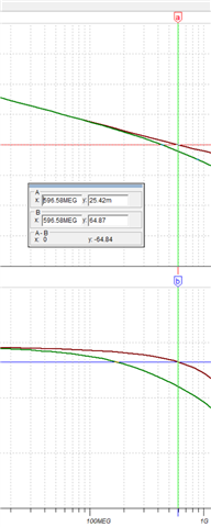
I compared the input characteristics of the FDA (above) with how I interpret the datasheet values for input impedance (below) :

image.png

My results are that the pole frequency varies by 10x, indicating that the input capacitance of the model seems to be 10x smaller than my equivalent circuit:

image.png

This leads me to the following questions:

  • Am I understanding the input impedance values correctly and if so, why does the model not integrate the correct values?
  • If my understanding is correct, how does the FDA manage proper phase margin without feedback capacitors to introduce a zero? Does the FDA include any internal compensation, maybe a zero around this frequency to cancel the effect of the pole (I doubt that this is the case, but who knows)?
  • What is TI's opinion about using SMALL feedback capacitors to add a zero to improve stability? I mention small values as I know that high speed op amp do not like driving capacitive loads and adding the lead compensator adds capacitance to the output, when considering the input capacitance of the op amp itself.
  • Does TI have a SPICE model dedicated to the -SP version? The model is the same as the commercial part, but the CFP packaging must add parasitics that probably matter at those frequencies.


Best regards,

Vincent

  • Hello Vincent,

    I am glad to look into this behavior for you.

    I do have a critical leading question: can you look at the THS4511 netlist for the SPICE model?  I need to know which version you have, as we have multiple versions and the version or type of model will directly impact how the input impedance is represented.

    The differences between the two are numerous, but for your actions I just need to know if you are working with a 'Copyright 2011' model or a 'Copyright 2019' model.

    Thank you Vincent!

    Best,

    Alec

  • Hello Alec,

    I am using the version directly integrated in PSpice for TI. When looking at the THS4511.lib file in the installation folder I can see that it is the copyright 2011 version.

    Vincent

  • Hello Vincent,

    Okay, thank you!  Would you be able to try your same experiments with the 2019 model version?  I know it is not pre-packaged with PSPICE-FOR-TI, but it is validated and available for the THS4511 on the web, although only for TINA-TI.  Instead of asking you to rebuild everything in TINA-TI, I am attaching a properly set-up version of the 2019 model for PSPICE.

    Overall you will find many examples of the TINA-TI models being updated but the PSPICE models being older.  This is also true for the internal TINA-TI library within the program; the best way to get an updated model is to check the TI product page and download the most recent model regardless of simulator.  The import/setup process for using TINA and PSPICE models with each other is not so difficult, which may help you in future designs.  Of course, you are always more than welcome to bring it to our attention and ask for help as you need it, even for a quick conversion.

    Please test this model and see if it suits your needs.  The input impedance, the capacitance portion, is lower for the THS4511-SP than the catalog THS4511, per the datasheet specifications.  


    THS4511_Update_2019_PSPICE.zip

    Best,

    Alec

  • Hello Alec,

    Thank you for providing this information and troubleshooting steps.

    I tested with your zip file, I have the same behavior with regard to the input impedance.

    I also tested TINA-TI, which also behaves the same (impedance of the model seems too small).

    For reference, here is how the loop gain changes when manually adding the input impedance of the datasheet:

    The phase at the 0dB frequency goes from 65 degrees

    to 35 degrees

    35 degrees is too low for comfort, especially when considering that this is with the THS4511 which I expect to be much more stable than the THS4511-SP for a few reasons:

    • THS4511 Gain product bandwidth is 2GHz instead of 3GHz for the -SP variant.
    • THS4511 is unity-gain stable whereas the -SP variant requires a gain of +6dB (which makes sense considering the -SP variant has a higher gain-product).
    • Packaging is different. CFP package are bulky and behaves worse at high frequency. This point might be the reason for the difference shown in the previous 2 bullet points.

    All of this leads me to think that even reaching 35 degrees of phase margin is optimistic for the THS4511-SP.

    Considering all this, my initial questions still hold.

    Thanks for your support,

    Vincent

  • Hello Vincent,

    Thank you for your follow-up and continued analysis.  I will commit to working on this for you to a resolution.

    Please allow me time to investigate further; I expect to update you early next week on progress and final results.

    Best,

    Alec