TL082: TL082IDR and TL084IDR related issues

Part Number: TL082
Other Parts Discussed in Thread: TL084

Hello,

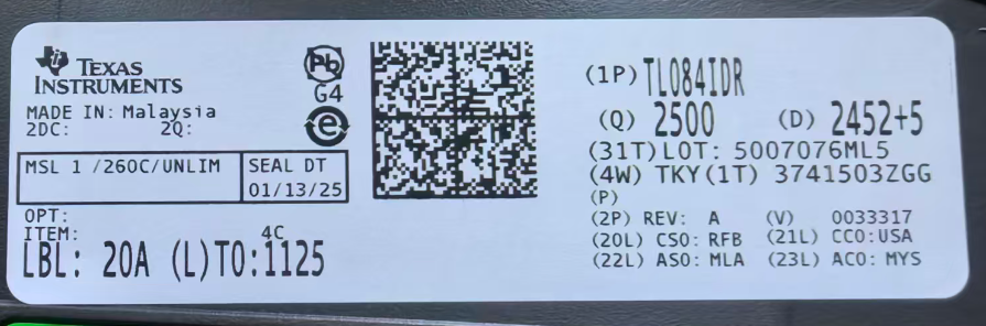
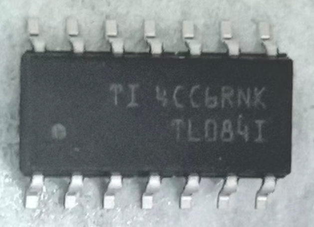
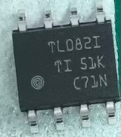
The quality flowmeter product uses TL082IDR and TL084IDR operational amplifiers, and there are issues with a single batch of products. Operational amplifiers can affect the 3.3V power supply of the system, causing voltage fluctuations between 2.8V-3.3V. There is no problem switching to other batches of products. Different batches of chips have different silk screen printing. The operating voltage of the operational amplifier is+/-9V, and both 3.3V and+/-9V voltages are converted using 5V voltage. 502 chips were soldered separately, but all had related issues. The chip label is shown in the following figure. Please help analyze the cause. Thanks.

003.png001.png

002.png

004.png

  • Hello,

    We can try to help but there is still some confusion about this issue.  Can you clarify: there are issues with both the TL082 device and the TL084 device?  Also, you mentioned that other "batches" work, do you have the date codes of the previous devices that do work?

    We'll need a schematic and some data to help us debug this issue.

    If you can provide this, we'll see what we can find.

    Regards,
    Mike

  • Hello,
    The date code for the TL082IDR problem chip is 2504, while the date code for a normal chip is 2226.


    The date code for the TL084IDR problem chip is 2452, while the date code for a normal chip is 2312.


    The customer is unable to provide a schematic diagram. Thanks.

  • Hi Jeno,

    Ok, those are likely new die for the new date code.  The PCN below describes that the TL082 would be moving to a new fab:

    https://www.mouser.com/PCN/Texas_Instruments_PCN20220615003_20220616135610237.pdf

    There are some minor differences in the die; the data sheet describes most of them (the "H" die is the new die in the data sheet, both the old and new die performance differences are listed in the data sheet).

    The only other difference not mentioned in the data sheet is the ESD cells on the input  The old die did not have an ESD cell to the positive supply, see below:

    Hopefully this helps, let me know if you can get the schematic and we can get a closer look. 

    Regards,
    Mike

  • Hello,

    The customer schematic is shown below, and the signal input impedance has changed after adding "clamping diodes". It should not be suitable for use. Please help analyze. Thanks.

  • Hello,

    This circuit should still work as it has previously, as long as the input signals do not exceed the supply voltage.  Can you tell me how they are measuring input impedance?  Is it with the board powered up, or unpowered?

    Regards,
    Mike