CSD19536KTT: Turn ON limit of the MOSFET

Part Number: CSD19536KTT


Hello

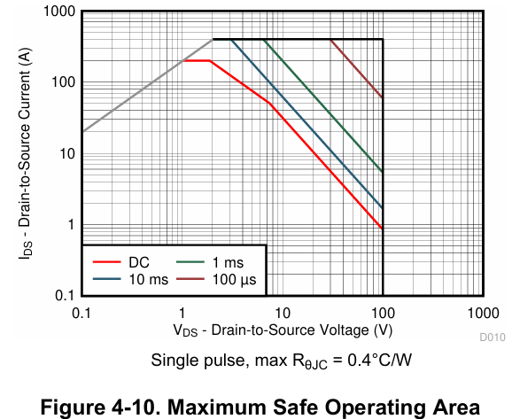
I would like to understand the SOA of the MOSFET. With a pulse current, the limitation is the junction temperature?

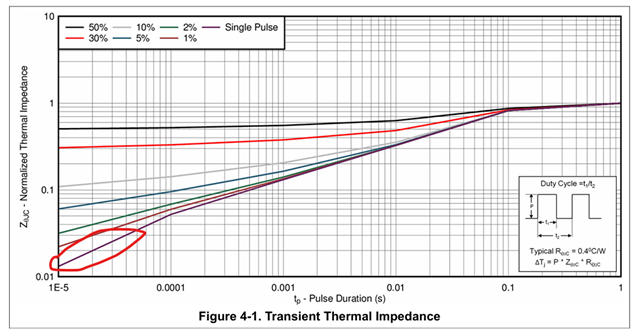
Does it have a thermal capacity & thermal resistance, which could provide a tau value to calculate the junction temperature with dedicated current value and current duration?

What I want to say is the ON state of the MOSFET.

Thanks!

image.png

  • Hello,

    Thanks for your interest in TI FETs. You will find links below to technical articles explaining how TI tests and specs SOA in our FET datasheets and how to use the SOA graph in a design. SOA is mainly a concern when the FET is operating in linear mode with voltage across it while current is flowing thru it. Junction temperature rise can be estimated using the transient thermal impedance graph in Figure 4-1 of the CSD19536KTT datasheet. Please review and let me know if this answers your questions or if you need additional information.

    https://www.ti.com/lit/pdf/SSZTCR5

    https://www.ti.com/lit/pdf/SLUAAO2

    Best Regards,

    John Wallace

    TI FET Applications

  • Hello John

    Thanks for your feedback. What I want to know is for the RDS(ON) limitation curve, for each current point, how long could the MOSFET withstand. I understand it is mainly related with the thermal resistance & thermal capacity of the MOSFET.

    Is there a formula with could indicate the pulse width / current relationship?

    Thanks in advance!

  • Hi,

    Thanks for the update. The end points of the Rds(on) limit line are calculated as follows:

    Id = Vds / Rds(on), where Vds = 0.1V and Rds(on) = max Rds(on) at 175°C = 5.09mΩ, Id = 0.1V/5.09mΩ = 19.66A for the left end point

    Similarly, for the right end point: Vds = Id x Rds(on) = 400A x 5.09mΩ = 2.04V for the right end point. 

    There is no pulse width involved in these calculations. The Transient Thermal Impedance (Zθjc) graph in the datasheet is used for pulsed power applications. I am including 2 links below. The first one explains the transient thermal impedance graph and pulsed power ratings. The second one is an application note on using the Zθjc graph in your design. Please review and let me know if you have additional questions.

    https://www.ti.com/lit/pdf/SSZTCJ6

    https://www.ti.com/lit/pdf/sluaat8

    Thanks,

    John

  • Thanks!

    It is quite clear.

    So I need to know the relationship between thermal impedance and duration.

    Generally, the curve seems linear in log axis.

    I do some calculation and get a result. In the linear area, especially when the duration is small.

    My result is I^4*t should be less than a constant to keep MOSFET safe.