TL074: TL074 : TL074CDR – Functional Failure After PCN# 20221219006.1 (FCT Fail on New Date Code 2436, 2443 & 2522)

Part Number: TL074


Hi TI Support Team,

I would like to request your assistance and clarification regarding a recent fresh yield issue observed on the TL074CDR operational amplifier, where we observe burn mark on the VCC Pin (V+,Pin 4) of the part (DC2443) after performing regular functional testing. The module passes after reworking with other date code. Some units didn’t reveal the sign of burnt but causing the power missing on module level functional test and show the abnormal sign of IV Curve Test. No changes in testing, layout, components, process, environment. We are encountering FCT self-test failures on product affecting 20% failure rate PCAs and 100% pass on DC 2327 and 2332 (Last good DC). There are 3 units per board and only U4 with rejects.


As a proactive measure, Our CM has done internal FA with the following initial conclusion. After troubleshooting, we isolated the root cause corresponds to TL074CDR :

1) External Visual Inspection: The package surface shows a localized burnt mark on the top side inspection, with cracks propagating around the burnt area.
2) De-capsulation & Inspection: Burnt marks and carbonized residues (darkened regions) were observed on the die surfaces.


Location : U4, U1 & U728


Date Code : (Good DC 2332, 2312 & 2327 vs Bad 2443, 2436 & 2522)

image.png

 
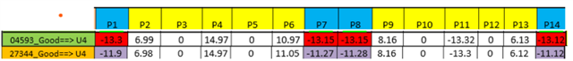
Based on the recent findings, there is an obvious difference between the older date code and the latest failing date code.

The output voltage (P1/P7/P8/P14) of the new Date Code parts(highlighted in red) rails to maximum of the negative VCC (-13V) supply unlike the older once (highlighted in purple) where it is 1 V lesser (-11.5v)

It happens to all the 3pc of the IC that is used in the PCA. (no load condition)


For additional, I manage to get the datasheet comparing old (Dec 2021 - pre PCN) and new datasheet (July 2025 - post PCN) and some significant changes can be observed after the PCN
 
Some of it on the gain bandwidth from 3 Mhz to 5.25 Mhz, input noise density at 1 kHz from 18nV to 37 nV and difference in functional block diagram
 
 
New Datasheet


Old Datasheet


For more details kindly refer to FA Req No : CPR251132476 

Thus, may I know, how does this difference can lead to this issue ?

 
Regards,
Arief
  • Hi Arief,

    You are correct, this is likely related to the PCN #20221219006. This device moved to a new process technology, and the failure you are seeing are likely due to updated ESD structures. The protection scheme has changed for this device, which is most likely why your functional tests are failing. For more information about this, please see Section 6 of the app note ESD Cells in Op amps

    Can you describe how the functional test is performed? If the supplies are left floating, you could be powering on the device, which could in turn unintentionally latch the protection cell in the op amp.

    Best regards,
    Carrie

  • Hi Carie,

    I am replying on behalf of Arief. Above is the condition of testing that causes the failure. Only 10-15 % fails. Fails means the +15V (P4) internally burns.

    Please advise what causes this failure and if there is any recommendation to avoid it

    Regards

    Suresh

  • Hi Suresh,

    The TL07X family has nontraditional ESD protection, which can be further explained in Section 3 & 4 of this application note. From the failure mode, it seems like you are latching the absorption device inside the op amp, which is why P4 internally burns.

    If the supplies are on during this test, you could be experiencing a power supply sequencing issue. I would ensure that you are turning on the supplies for the op amp before turning on your input signal, 8VA.

    Best,
    Carrie