This thread has been locked.

If you have a related question, please click the "Ask a related question" button in the top right corner. The newly created question will be automatically linked to this question.

AMC3301: Differential output over twisted pair

Part Number: AMC3301
Other Parts Discussed in Thread: AMC1200, AMC3302, OPA365

Hi Team,

Posting on behalf of our customer.

Would it be feasible to transmit the differential output of the AMC3301 (AMC1200 also applies) over a 12"-24" twisted pair 100-ohm ribbon cable ? The receiving end would be an instrumentation amplifier to convert it to single-ended for an ADC.  The datasheet doesn't appear to say much about the amplifier's stability. Would it make sense to add series resistors (10-50 ohm) on the AMC3301's output lines before sending over the cable?  I obviously won't be able to add a termination resistor at the INA's input because the AMC3301 wouldn't be able to drive the necessary current for that anyway.  The application will be a SiC-based motor inverter separated from the controller by this ribbon cable. 

Or would you recommend some sort of analog line driver to accomplish this?  But I hate to add the extra parts though.

Regards,

Danilo

  • Hi Danilo, 

    I do not have a personal experience with connecting such a long twisted pair ribbon cable to the output of any of our opamps. 

    However, I expect it will work well. Just recently, I used two 3m coax cables to bring the output of AMC3302 to an oscilloscope. 

    I suggest using 10 to 22 ohm resistors in series. I would even consider adding a very low capacitance (15pF) to the ground. This does not cause much filtering but may help with ESD events. 

    I agree about the termination. Of course, this is not going to be ideal termination for the reasons you shared, but terminating with e.g 1-10kOhm resistor should be fine. 

    Please note, that in all cases there will be likely a lot of noise coupling to the ribbon cable. Filtering on the receiving side has to be perfect. A typical difference amplifier with caps across the forward resistors may have a very bad CMRR. 

    Would you be able to sketch a system / circuit diagram such we could review the recommended solution?

    Kind regards, 

    Jiri Panacek, Systems Applications Engineer, ISC

  • Hi Jiri,

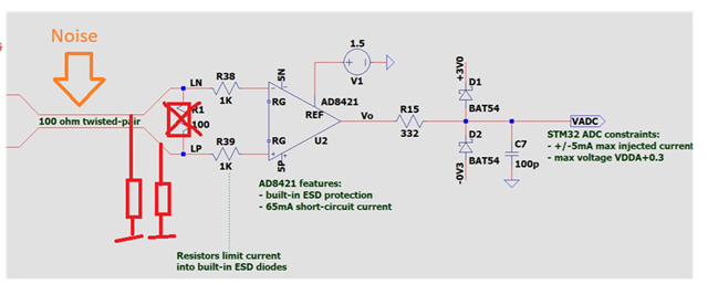
    I'm the one who posted original question, and thank you for your response.  Below is a sketch of what i'm trying to do. The AMC3301 will read the motor phase shunt. I may need to choose a different INA to accomodate the voltage range, but it's just there to show that I'm converting to single-ended.  Since i'm planning to sample current during the "quiet" window of each switching period, I'm hoping to squeek by not having to apply too much analog filtering so as to not prolong the settling time. The signal will reside on a 40-pin ribbon cable (with twisted pairs) which will only contain other differential analog pairs and RS422 pairs for control. But it won't contain any direct motor di/dt or dv/dt content, other than what will get coupled over the air I'm guessing.  With that said, do you filtering will still be as critical?  I've certainly heard of matched termination, but I haven't heard of terminating with higher values (1-10Kohm) as you mentioned.  Appreciate the help!

    Zackary Long

  • Hi Zackary, 

    thanks for sharing. I have a few things for you to consider. 

    The circuit diagram for the AMC3301 is correct. Nevertheless, please consider ferrite beads (0603 package) at the locations as I highlighted below. By default, use 0-ohm resistors there. These ferrite beads occasionally help with high-frequency noise coming from the power lines (motor phases).

    Regarding the instrumentation amplifier (AD8421 or similar). This is a good looking device and our friends from ADI did a good job. In your application it is important to have an effective common mode rejection ratio over a wide range. I see that this device still achieves 60dB at 200kHz. This is good.

    What I don't like much are the protection diodes with BAT54. These are shottky's and they leak current. This leakage varies with temperature and applied voltage.  BAT54 has multiple manufacturers and decent one's also publish typical plots in the datasheet.

    (courtesy: Vishay)

    In case both diodes leak the same current, then there is no problem. However, as you can see, when the output voltage of the INA is close to its maximum or minimum, one diode sees reverse voltage of nearly 0 whereas the other one sees e.g. 3V. This is when the error comes in play. I believe, in your application, it won't make difference, but it would be unfortunate to pay premium for INA and then compromise its performance by the diodes on the output. 

    I think, protection at the inputs of the ADC is generally not needed, especially when the opamp (INA) is close to the pin. In case you still want to protect the input, have a look at our diodes. They are not mainstream, but have extremely low capacitance and leakage current even over temperature.

    Example:

    https://www.ti.com/product/TSD03

    https://www.ti.com/product-category/passive-discrete/diodes/esd-protection-diodes/overview.html

    https://www.ti.com/product-category/passive-discrete/diodes/tvs-diodes/overview.html

    Don't get confused that most of them are intended for USB bus or similar. They work for analog as well. :-)

    In general, we see our customers using a discrete difference amplifier for converting the differential to single-ended signal for the ADC. Please refer to the appnote that I recently published: https://www.ti.com/lit/an/sdaa114/sdaa114.pdf

    Regarding the termination.... well, let me walk on a thin ice here... Slight smile

    One of the key differences between the INA and the difference amplifier (OPAMP + 4 resistors) is the input impedance. Difference amplifiers have un-buffered inputs and for this reason, both the single-ended as well as differential impedance is in the range of tens of kilo-ohms. A proper INA has a buffered input with ~1GOhm input impedance. 

    Noise coupling to the signal wires between the AMC and INA generates tiny current. This current has to find a path back to the source. In case there is a high impedance path, this current creates a higher voltage drop therefore higher error.

    I recommend adding something like this to the input:

    I would start with 10k resistors. What it does is following: 

    * in case the cable is disconnected, the inputs of the INA are properly biased and do not float. The Vo will remain zero.

    * common mode noise  coupled to the cable will pass through the resistors to the ground. (instead of through the INA input capacitance).

    What I do not recommend is adding capacitors to the differential signal path.  Caps have way higher tolerances than resistors and often make things worse. Let the INA's CMRR capability to do the job. Start adding caps later on if you encounter problems.

    PS: I used previously a word "termination". Termination is used more in the context of impedance matching for high-frequency signals. The signal from the AMC device will be rather slow due to its limited bandwidth. For this reason, there is no concern about signal reflection, etc. 

    In this case, I would rather think about "controlled path" for the common mode and differential noise. I probably should not used the word "termination". 

    I hope this helps!

    Best regards, Jiri

  • Jiri,

    Thanks for the excellent information! I plan to implement all design points you made here.  Do you recommend the differential resistor be 10K also?  Simulation shows that the AMC1200 is sensitive to output loading so there is a little bit of error with 10K resistors (~10mV loss), but I think I'm willing to accept that.

    I read your app note a couple times, and was super helpful. But there's something I've never quite understood about these external RC filters used on ADC inputs, and maybe you can clear this up for me. If the amplifier is chosen to have a high enough bandwidth (OPA365) to settle out the external RC filter, then what's the point of the RC filter?  If the amplifer's bandwidth is high enough to settle the entire network, Rb-Cb-Csh, then it should be able to settle the network fine without Cb, less total capacitance.  So why is Cb needed?  If it can fill a Cb-Csh charge bucket, then it can fill a Csh charge bucket.  I'm sure there's something fundamental i'm missing here.  

    If Rb-Cb is to be used as an anti-aliasing filter, then I think that would make sense, however another TI video mentioned that it should not be used for that purpose. It said that anti-aliasing should be done in another filter upstream with a much lower cutoff.

    Thank you,

    Zackary Long