Part Number: XTR117
Other Parts Discussed in Thread: XTR116,
Hi,
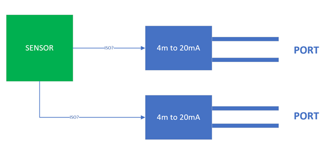
I’m working on a circuit design that requires two current-loop outputs:
-
Channel 1: Standard 4–20 mA output
-
Channel 2: An inverted 20–4 mA output
(meaning: when Channel 1 outputs 20 mA, Channel 2 should output 4 mA, and vice-versa)
I have already found several TI reference designs and application notes for generating a standard 4–20 mA output using devices like XTR116 / XTR117.
However, I could not find a clear method or reference for generating the inverted 20–4 mA loop.
My questions:
-
What is the recommended approach to generate an inverted 20–4 mA output?
-
Is there any TI reference design, application note, or suggested device for implementing this?
-
Should the inversion be done by signal conditioning on the voltage side (e.g., mapping 1–5 V → 5–1 V) before feeding the current transmitter IC, or is there a more direct method?
Any guidance or example circuits would be greatly appreciated.
Thank you!