


Part Number: LM7171
Hi Team,
Here is the circuit diagram that has been provided in the ATE Hardware setup.
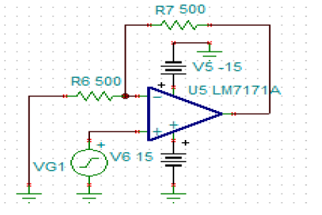
There is a 50 ohms isolation resistor in the output pin of LM7171. (As per the recommendations given in datasheet in order to overcome the overshoots and undershoots due to high capacitance)
There is a BNC connector given after the isolation resistor, where the BNC cable is connected and the other end is connected to the instrument.
The board setup has Tester -> Loadboard -> Socket card.
The circuit and BNC connector is present in Socket card. The cable is connected to BNC connector in loadboard. Then there is a cable inside the tester from the pogo pin of the tester to the instrument front panel which is placed inside the chassis in the test head. There is a load capacitance seen due to the length of the cable. (Two cables -> One from socket card to Load board and the other one from loadboard pogo pins to the instrument front panel)
The OPAMP supply voltage is +/-15V and the input voltage is 5Vpkpk.
As per the below plots given in the datasheet, the slew rate must be ~2200V/us.
But, in the ATE setup, I am measuring the value of 1400 - 1700 V/us.
Trying to understand the reason for not measuring around 2200 V/us. Is it reduced due to high load capacitance?
One general question - Is the plot given for Slew rate vs Load capacitance, is that applicable for the lumped capacitance and distributed capacitance? In my case, there is no any cap connected from output to GND (which is lumped), but the long coaxial cable will definitely have a load capacitance which is distributed..Measured ~130pF between output pin to GND. Assuming 130pF as the load cap seen due to the cables. Please provide any explanations on the above case.

Thank you
Pavithra Joshi
