Part Number: INA186-Q1
Other Parts Discussed in Thread: INA186, INA240
Hello, when we were using the INA186A2QDCKRQ1 with a gain of 50, we found that there was a significant deviation between its input and output results.
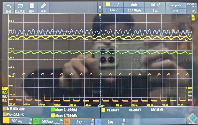
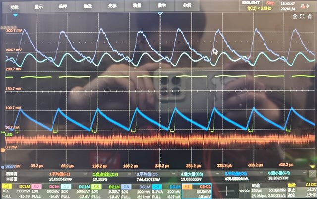
VPWR is 13.51V, the coil resistance is 5.1 ohms, driving the low-side MOS at a frequency of 16 kHz, and we tested waveforms with duty cycles of 9%, 18%, and 27%, but the input-output error is very large.
9%: Theoretical current value = 13.51 / 5.1 * 9% = 0.238 A; INA186 output = 0.173 A; Actual measured current via clamp = 0.137 A
18%: Theoretical current value = 13.51 / 5.1 * 18% = 0.477 A; INA186 output = 0.555 A; Actual measured current via clamp = 0.394 A
27%: Theoretical current value = 13.51 / 5.1 * 27% = 0.715 A; INA186 output = 0.911 A; Actual measured current via clamp = 0.635 A
We also checked the PCB layout and used Kelvin routing, so please help investigate why the output error of the INA186 is so large.

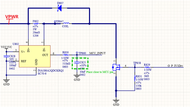 Circuit
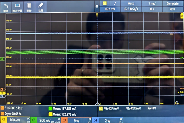 18% duty