This thread has been locked.

If you have a related question, please click the "Ask a related question" button in the top right corner. The newly created question will be automatically linked to this question.

INA226: VBUS connection

Part Number: INA226

Dear Technical Support Team,

According to datasheet, VBUS connnect IN-, but my understandig it VBUS connect IN⁺side generally.


image.png


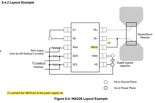
The VBUS pin is intended to measure the bus voltage
before the load.
(High-side sensing)
In the datasheet example, VBUS is connected to the IN- pin side below the shunt resistor.

The shunt voltage is understood to be measured as the potential difference between the IN+ pin and IN- pin.

I would like to check the circuit diagram. Would it be possible to send it via private message (friends) or email?

Best Regards,

ttd

  • Hello ttd,

    You can actually connect the VBUS to either IN+ or IN-, depending on what you want to measure. If you connect it to IN-, that gives you load power only. If you connect it to IN+, then that gives you system power (which is the load power plus the power dissipated over the shunt resistor). So it really depends on what you want to measure. 

    I've sent you a friend request so that you can send me the circuit diagram for review.

    Regards,

    Mitch