This thread has been locked.

If you have a related question, please click the "Ask a related question" button in the top right corner. The newly created question will be automatically linked to this question.

INA148: Impedance question

Part Number: INA148
Other Parts Discussed in Thread: TINA-TI

Hi, we decided to use the INA148 with as a replacement of AD8479 Datasheet and Product Info | Analog Devices.
Currently, our design uses 2 pull-ups of 200k. One for each INA148 inputs, one connected to +13.5V and the other to -13.5V.
The INA is power by the same rails: VS+:13.5V, VS-:-13.5V as depicted below.
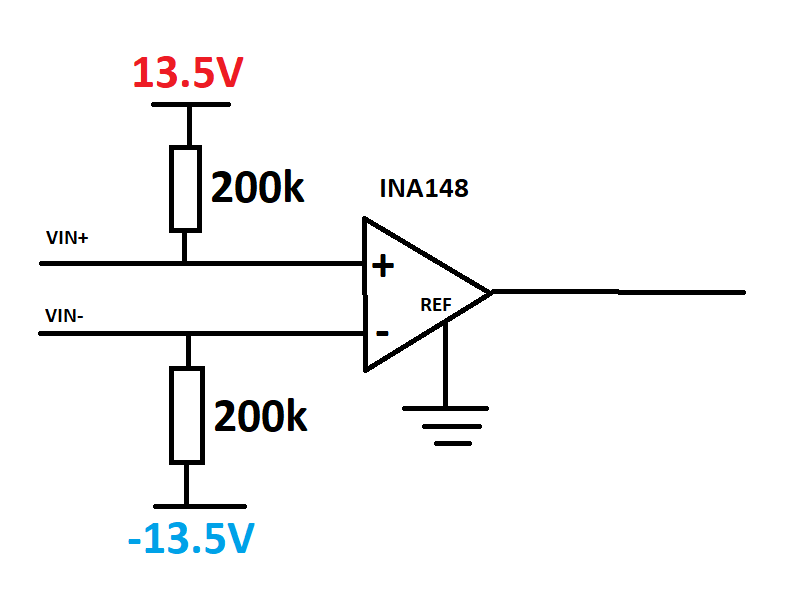
image.png

The resistors are used for a wire-detection feature. 
Our concerns is if those resistors of 200k can affect the behavior of the INA. Our main concerns is mismatching of influencing the input impedance.
Could you please provide us some input related to this situation?

Best Regards,
David CONDOR


  • Hi David,

    Because the mismatch is not a difference in source impedance that is a part of the signal path, the CMRR and transfer function are not significantly affected.

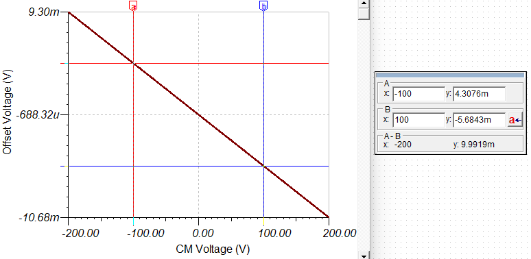
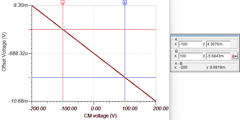
    Below are some TINA-TI simulations showing the transfer function and CMRR with and without the pullup/pulldown resistors that have a worst case 1% tolerance mismatch (one is 202kΩ and the other is 198kΩ).

    • Output voltage with -5V and 5V input voltages (without pullup resistors):
    • Output voltage with -5V and 5V input voltages (with pullup resistors):
    • CMRR (without pullup resistors):
    • CMRR (with pullup resistors):

    However, these simulations were done with ideal voltage sources at the inputs. What you do need to worry about is the drive strength of the input voltage source. If the source has low impedance, most of the bias current will flow directly into the source, and the mismatch between the resistors will not cause significant error. If the source has high impedance, there will be higher error introduced by the inclusion of the pullup resistors.

    If you know the rest of the circuit, you can simulate with TINA-TI as I did above or with PSpice for TI, and you can find links to SPICE reference designs and models for the INA148 here under "Design tools and simulation". It will be able to simulate any error introduced in your circuit.

    As a side note, for the wire-detection, will there ever be a state where VIN+ will be pulled up to 13.5V and VIN- will be pulled down to -13.5V at the same time, and therefore the difference amp will have a differential voltage of 27V? If so, you will be limited by the output limitation of the device. 

    Best Regards,

    Taylor Allan