This thread has been locked.

If you have a related question, please click the "Ask a related question" button in the top right corner. The newly created question will be automatically linked to this question.

OPA140: OPA140 Tina simulation

Part Number: OPA140

Hi,

I try to use OPA140 to design my circuit. When I build a inverter amplifier, the result looks not correct. image.png
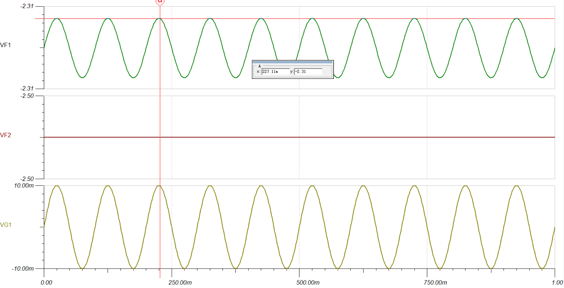
I am not sure it is because of the supply voltage for omamp too small. When I increase to ±10V, it looks work well. But in the datasheet, I think ±2.5V can meet the requirement.

image.png

I put my simulation file here.

Best,

Junzhe

OPA140.TSC 

  • I think it is may because of the supply voltage, I tried to change my supply voltage to ±5V, it can works well. 

  • Hi Junzhe,

    In your current setup, you are violating the input common mode range. The OPA140 has a common mode range of (V-) - 0.1 < Vcm < (V+) - 3.5V (see below).

    Since V+ = 2.5V, and V- = -2.5V, the input common mode range is -2.6V < Vcm < -1V. Since you have grounded the non-inverting node, we know that Vcm = 0V, which is in violation of the input common mode range. Even if you were within the common mode range, your circuit is in a gain of -10. Therefore, an valid input voltage would violate the output limitation of the op amp. Note below that an input voltage of Vin = -1V is valid if the gain of the circuit is within the linear output range.

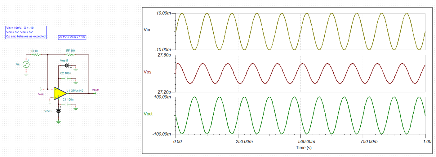
    The simplest way to fix this problem is to increase the voltage supplies, as you discovered. If the supply voltage is increased to +/-5V, then the input common mode range changes to -5.1V < Vcm < 1.5V. 

    This allows the input common mode value of 0V to be valid, and the op amp behaves as expected. I have attached a simulation with my results. Please let me know if you have further questions.

    Best regards,
    Carrie

    opa140_vcm_violation.TSC