This thread has been locked.

If you have a related question, please click the "Ask a related question" button in the top right corner. The newly created question will be automatically linked to this question.

TLV9062-Q1: Connector mating detection circuit

Part Number: TLV9062-Q1
Other Parts Discussed in Thread: TLV1812-Q1, TLV9061-Q1, SN74LVC1G14-Q1, SN74LVC1G17-Q1

I'm designing a connector mating circuit as shown in the figure below. The connector will be inserted at the HVIL+ & HVIL- terminals. When the connector is not inserted the op-amp output will be low and when the connector is inserted, the op-amp output will go high.

Is there any problem with this circuit? In the simulation the output seems fine.
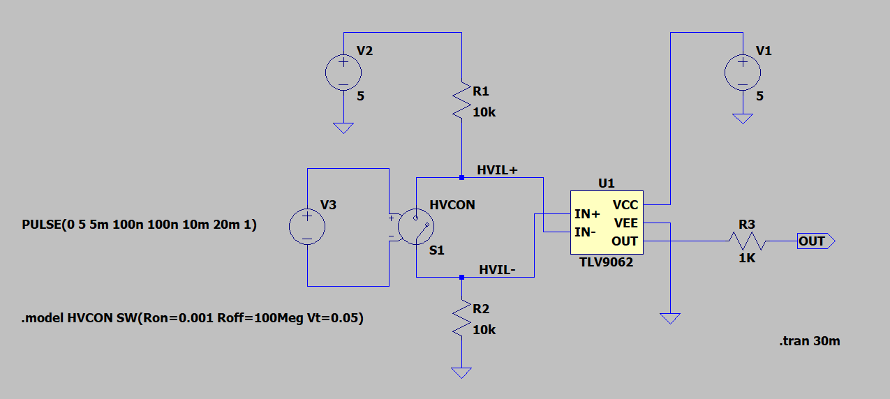
image.png

  • What are the voltages at HVIL+/HVIL− when the connector is inserted?

    The TLV9062-Q1 can be used as a comparator, but unless you need to use the second channel or an analog signal, an actual comparator like the TLV1812-Q1 or TLC7032-Q1 should be preferred.

  • The connector will be mated at HVIL+ & HVIL-, which will short out these two nets. There is no voltage for these nets. Here since i only need a single channel, I'm actually using a TLV9061-Q1.

  • When the voltages at the IN+ and IN− pins are the same, then the output of the comparator is undefined. This is not guaranteed to work.

    Connect HVIL+ with a pull-up resistor to 5 V, like now. Connect HVIL− directly to ground. Now the voltage at HVIL+ is either 5 V or 0 V. Connect that to the input of a Schmitt-trigger logic gate like the SN74LVC1G14-Q1 or SN74LVC1G17-Q1. (The input signal needs strong ESD protection, and it might make sense to add an R-C low-pass filter.)

  • Preerag,

    Can I assume HVIL inputs are never close to the same voltage? What is the input signal when connected? Is the input source floating as shown in the diagram?