This thread has been locked.

If you have a related question, please click the "Ask a related question" button in the top right corner. The newly created question will be automatically linked to this question.

INA826: Ina826 magnification is inconsistent

Part Number: INA826

Hi Teams,

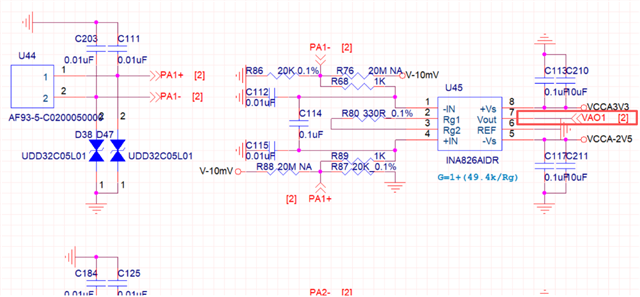
The customer is currently using the INA826AIDR operational amplifier and has discovered an issue. According to the design in the diagram, the amplification factor should be changed to 150.7. However, it has been found that two chips have been replaced at the same position on the same PCB, and the amplification factors of the two chips are not quite the same, one is 149 and the other is 148. May I ask if this is an inherent error of the chips?
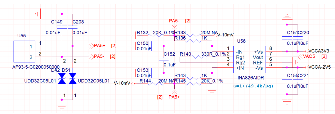
image.png

  • Hi Vayne,

    I'm glad to hear you did a swap test. That's what I would have recommend first doing. 

    The fact that you are seeing a larger difference in the gain than expected is also strange. What is the tolerance of the gain resistor? 

    Would you be able to share the layout of the board? I want to eliminate this as a possibility of a reason we are seeing a difference in the gain settings. 

    Also how exactly did you calculate the gain of the system? Just to verify. 

    Thank you,

    Robert Clifton 

  • Hi Robert,

    Thank you for your reply,

    The resistance is 330R/0.1%,PCB as attached,

    WZ_METEOROLOGICAL_COLLECTIONPCB_V1_2_20251219p1_finish.zip

    The gain is calculated according to the formula given in the datasheet.

    Thank you!

    BR~

  • Hi Vayne,

    I forgot to ask where you measured the output of the system?

    Based on my calculations purely from the resistor tolerance, I find the measurements of 148 and 149 gain highly suspicious. I'm not saying your calculations are wrong I just think there might be something else going on here besides the fact that they are changing so wildly between units. 

    Best Regards,

    Robert Clifton 

  • Hi Robert,

    The measured value is the ground voltage of VOUT.

  • Hi Vayne,

    Robert is currently out-of-office, so I will be covering this thread while he is out. I agree with Robert that the gain error in this case is unusually high, taking into account both resistor tolerance and internal gain error.

    Is the gain being measured by a DC sweep of the input voltage and measuring the slope of the output voltage vs. input voltage? If not, I would recommend doing this as it separates the DC offset from the gain error calculation. Also, do you know the voltage ranges of PA1- and PA1+?

    Best Regards,

    Taylor Allan