This thread has been locked.

If you have a related question, please click the "Ask a related question" button in the top right corner. The newly created question will be automatically linked to this question.

TPA2039D1: Haptic driving could not work

Part Number: TPA2039D1

Hi BU, 

My customer is using TPA2039D1 in the gaming chair application to create haptic feedback for his product. 

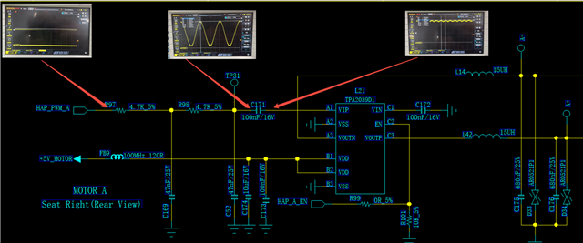
In the second figure, the original value of C171 (corresponds to C286) = 0.1uF, C169 (corresponds to C284) and C52 (corresponds to C285) = 68nF. Customer has just updated the values like what are shown in second figure. 

1.png

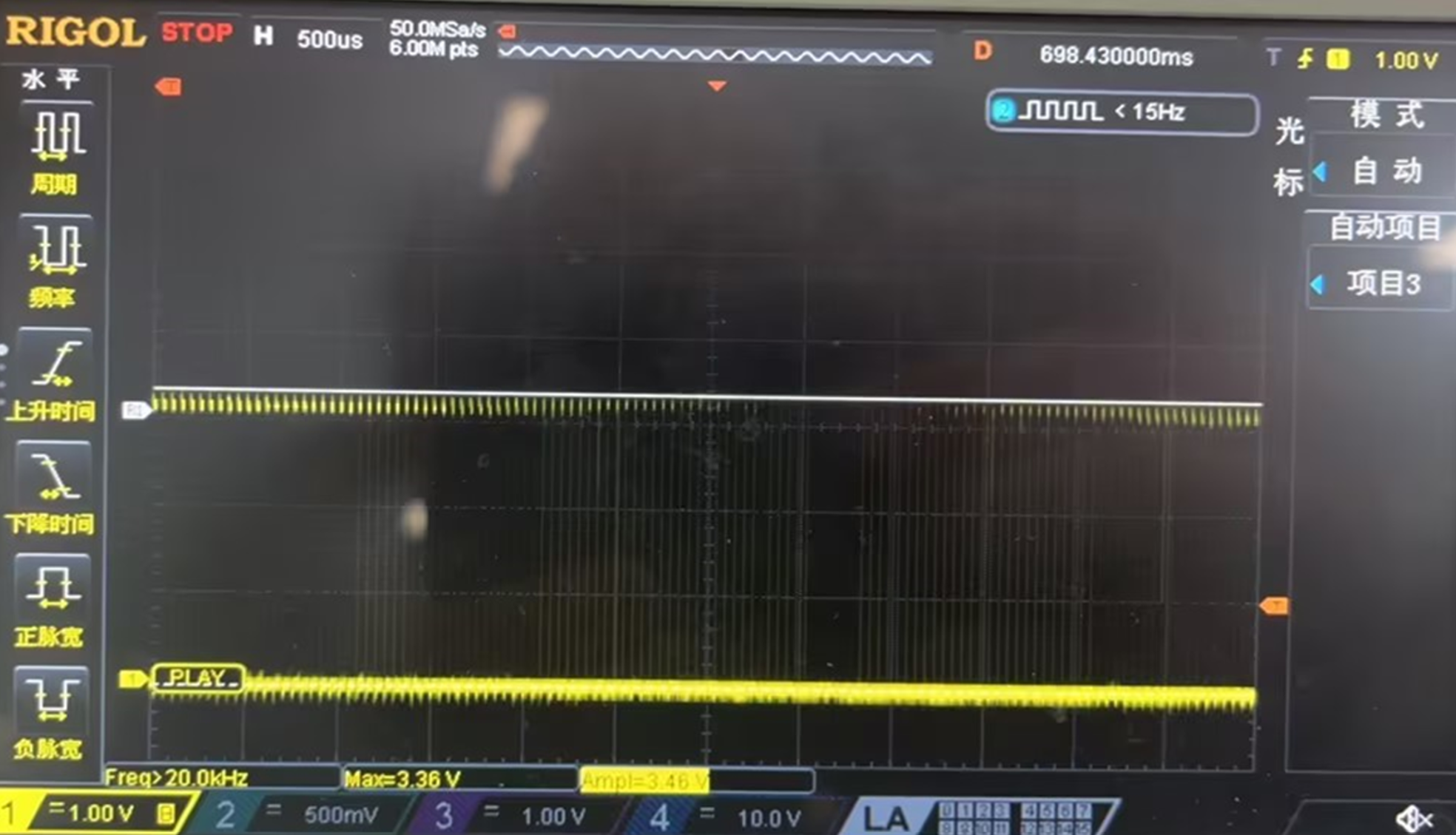
The input is a PWM signal. 

3.png


After the first and second RC filter, it will have a 50Hz signal. 
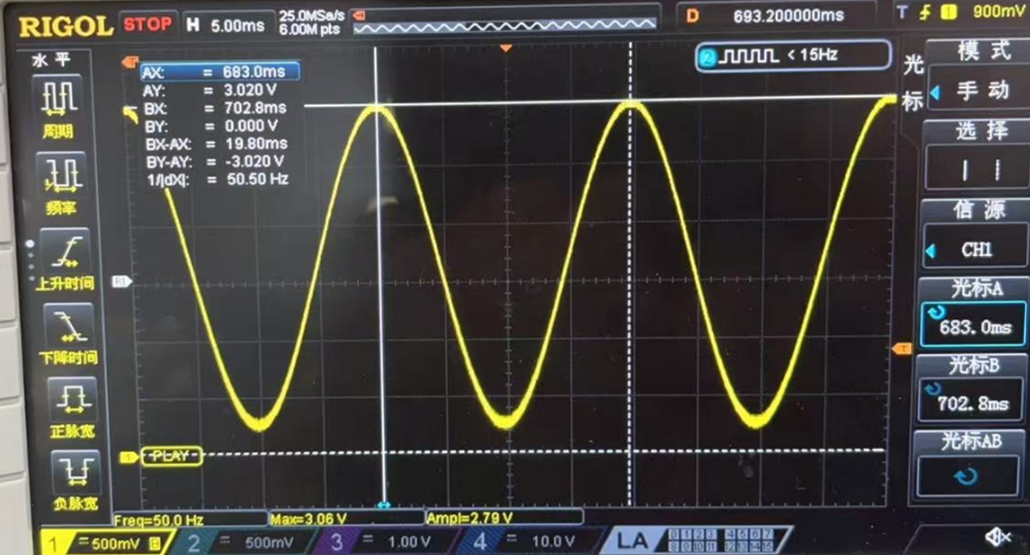
4.png


However, after passing through C171 = 0.1uF, the signal became like below, causing the haptic driving could not work. 


Help needed:

  1. Can you help to check if there is anything incorrect of component placement at the input side? 
  2. Can you help to check if there is anything incorrect for input signal just before entering VIP pin? 


Thank you!
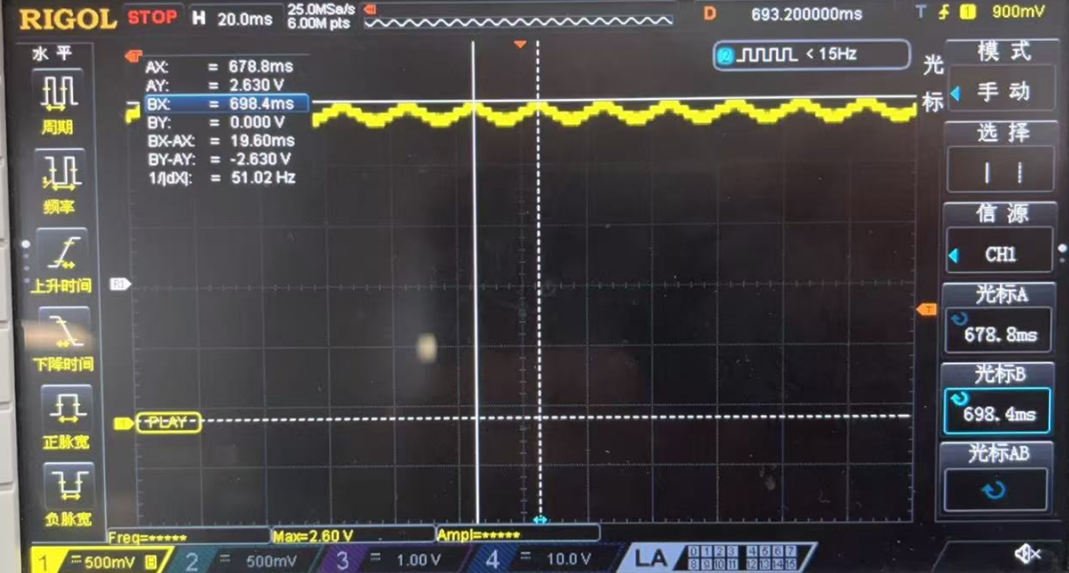
5.png

Regards,

John

  • Hi John,

    In analog input amplifiers the input C and R components form a high-pass filter, it is possible that you have to increase the value of the input C.
    I'll read the description in detail and get back to you with further comments by tomorrow.

    Best regards,
    -Ivan Salazar
    Applications Engineer

  • Hi Ivan, 

    Thank you for your initial response. I am sorry I forgot to attach the updated schematic diagram below. 

    Regards,

    John

  • Hi John,

    Thanks for the additional information.

    After checking the component values, it seems that input capacitor value should be OK for a low enough cutoff frequency of the high-pass filter. You can ignore that from my previous reply.

    Is this something they're seeing only on the second version but not on the first one?
    Would it be possible to remove the 47k resistor and feed an analog signal at the input side of C171 to check if the same behavior persists?

    Best regards,
    -Ivan Salazar
    Applications Engineer

  • Hi Ivan, 

    Good day to you!

    They are seeing similar issue for both first and second version. 

    After following your suggestion (removing first filter), the issue still persists. The signal after the coupling capacitor becomes flat but not sinusoidal. 

    Do you still have any suggestions coming into mind? 

    Thank you!

    Regards,

    John

  • Hi John,

    I'll check on this again and let you know if any further ideas by tomorrow.

    Best regards,
    -Ivan Salazar
    Applications Engineer

  • Hi Ivan, 

    No problem, thank you so much. 

    Regards,

    John

  • Hi John,

    Please try using the inverting input on pin C1 instead of pin A1. You can try leaving one side of C171 and C172 floating, then connect that floating side of C171 to GND and floating side of C171 to TP31.

    Another thing you may try is disconnecting the output; leave it floating or remove the 15uH inductors. Wondering if the output components may be affecting the feedback of the amplifier. Still, I think the first test of using inverting input is higher priority than this later one.

    Best regards,
    -Ivan Salazar
    Applications Engineer