This thread has been locked.

If you have a related question, please click the "Ask a related question" button in the top right corner. The newly created question will be automatically linked to this question.

LMH6518: LMH6518 configuration

Part Number: LMH6518

Dear 

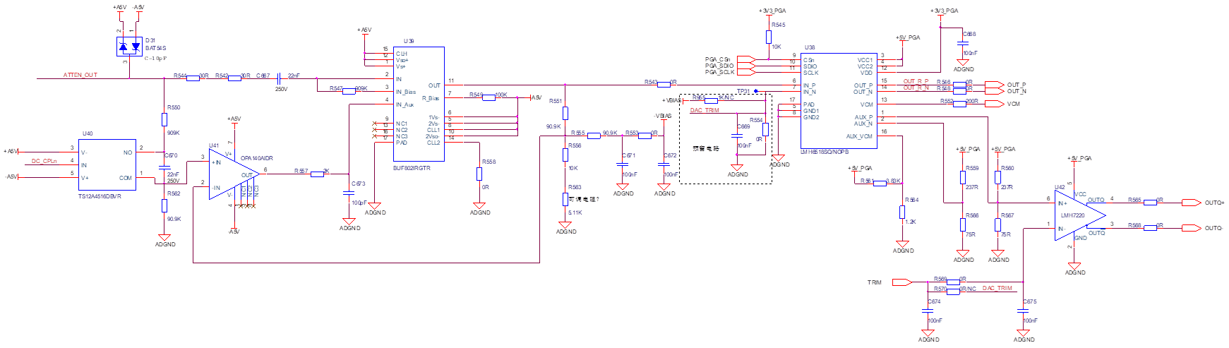
   The LMH6518 outputs a differential voltage of 1.5/1.8V when powered on by default. According to the manual, its internal gain (LG, -20dB +8.86dB) is 0.877 under default configuration, which does not match the observed phenomenon.

Attempt to directly configure the gain to (LG, -20dB+8.86dB) through SPI without changing the phenomenon, which can provide a method for using the 6518 configuration register;
1.png

  • Hi,

    For the default gain value, it is Lg - 20 + 8.86 which is around -1.14dB. Can you share what gain value you are seeing? I would also like to confirm the IN_N input is not shorted with R554.

    Best Regards,

    Ignacio

  • Under default configuration, the ratio of differential output to differential input of LMH6518 is measured to be 1.5 to 1.8. The differential input range is -0.8 to 0.8 vpp

    Reply 2. There is no short circuit at resistor R554. The resistor is not mounted on the actual PCB, but in fact, LMH6518 has a fixed 2.5V voltage at the in1 pin.

    Is there a similar enable for the LMH6518 chip? Is there still a DC bias effect that requires subtracting a bias from both the input and output? Please help confirm.

  • Hi,

    I believe what might be happening is that the LMH6518 has internal 50Ohm series resistors which expects 50ohm termination resistors out of each output. The gain calculation (LG, -20dB+8.86dB) I believe assumes you have this termination. Meaning if you don't, you add 6dB to these final gain numbers. If your ratio is 1.5V/V to 1.8V/V, this explanation might make sense. 

    Regarding your second question, can you explain what is meant by similar enable? With regards to the DC bias effect, the device's inputs should be centered around 2.5V. Any dc difference between the inputs will also get gained up at the output. The outputs are centered around your VOCM, which should be around 1.2V. There are not any sort of DC bias affects that would affect the output voltages, other than your DC bias input voltages not being close to equal.

    Best Regards,

    Ignacio

  • Is it about replacing R546 and R548 with 50Ω resistors? This doesn't solve the issue; the symptoms remain the same

  • Hi,

    It would require a 50ohm to ground connection or 100ohms differential across the two outputs. If this is not an option, you can always try to change the gain setting to the next value (atten -18dB) and see if the gain is also 6dB off from the expected.

    Best Regards,

    Ignacio