This thread has been locked.

If you have a related question, please click the "Ask a related question" button in the top right corner. The newly created question will be automatically linked to this question.

THS4631: Recommend Solution for Fast Transient Current Monitoring

Part Number: THS4631
Other Parts Discussed in Thread: OPA818, TINA-TI, INA281

Hi experts,

Would you please review customer requirements and clarify if THS4631 is suitable or recommend other TI high speed op amp which needs to support gain > 20, input power supply can be 3V/5V/12V, bandwidth hope to be above 22MHz, application voltage range 0.6V to 1V, current range 0-52A and be able to dynamically monitor transient 1000A/µs?


BR,

Allan 

  • Hello Allan,

      Customer will need a higher bandwidth part to meet a gain of 20V/V (or is this 20dB?) at a bandwidth of 22MHz. For the current range specification, is this a current-sensing application with expected input voltage range to amplifier of 0.6V to 1V after a maybe shunt resistor? Or I think this would be output range due to the gain expected to be greater than 20V/V. Can customer clarify the type of application?

    Thank you,

    Sima

  • Hello Sima,

    Regarding the current-sensing requirements:

    1. Gain >= 20V/V(External or fixed configuration is fine) 

    2. Rshunt voltage will be 0.01mV ~ 60mV

    3. Current Slew Rate : 1000A/us(max)

    Could you recommend an OP-Amps that meets these requirements?

    In addition, I would like to know how to evaluate the required bandwidth for the OPA based on slew rate and signal requirements.

    Thank you,

    Sekai

  • Hello Sekai,

      With their system requirements, then shunt resistance is approximately 1.15mOhms and rise time of their input current pulse is around 52ns. In that case, the expected slew rate the amplifier would need to support for 1Vpp max output voltage will be at least 20V/us which is easy to achieve with our high speed amplifiers. 

      I would need to know their expected supply range especially if it will be single supply. From what we have here, I would recommend the OPA818.

    Thank you,

    Sima

  • Hi Sima,

    Thank you for your recommendation.

    For more details regarding our requirements:

    1. Gain >= 20V/V(External or fixed configuration is fine) 

    2. Rshunt : 0.1mohm or 1 mohm

    3. Current Slew Rate : 1038A/us(1A-->55A in 52ns) and 667A/us(1A-->12.1A in 16.64ns)

    4. Small Current Measurement: Need to measure as low as 100mA across a 0.1mohm shunt

    5. Supply Range: Single 3.3V/5V/12V 

    Do you have any recommendations for a bipolar supply?

    Is the OPA818 suitable for this application? 

    Thank you,

    Sekai


  • Hello Sekai,

      Thank you for meeting with us yesterday.

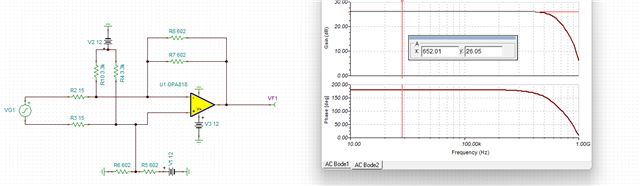
      Here is the circuit example using the OPA818 using your listed requirements:

      I did end up finding the board, I am talking to Allan offline for shipment.

    OPA818 Current Sense.TSC

    Thank you,
    Sima

  • Hi Sima,

    Thank you for your recommendation.

    If we increase the gain to 50V/V or 100V/V what circuit adjustments should be implemented or is there a way for us to calculate these ourselves?

    By the way, the circuit you recommended is for a gain of 20V/V, correct?  

    Thank you,

    Sekai

  • Hi Sima,
    Sorry, we cannot find the value for res=602ohm.

    1.Can resistors R5~R8 be 604or 620ohm in value?
    2.What functions will resistors R5/R6/R7/R8 affect?
     

    Thank you,

    Jim

  • Hello Sekai,

       If you increase gain to 50V/V or 100V/V you would have to change these resistors in the circuit above:

    • R7, R8, R2, R3, R6, and R5

      And, yes the circuit recommended is set for a gain of 20V/V: (26dB)

      I used the recommended RF value from the datasheet (301Ohms for a gain of 20V/V):

    Thank you,

    Sima 

  • Hello Jim,

       I apologize on my end I should have double checked with standard resistors before making the recommendation. 

    1. Yes you can use 604 or 620 ohm resistors, I would then change R2 and R3 to a bit higher if needed for an exact gain of 20V/V. 
    2. R5, R6, R7, and R8 are setting the gain of the circuit in the differential/difference amplifier case, you can think of these as the (RF value) and you can think of R2 and R3 as the RG value

    Thank you,

    Sima 

  • Hi Sima,

    If we increase the gain to 50V/V or 100V/V What values should be used for R7, R8, R2, R3, R6, and R5?

    Thanks. 

  • Hi Sekai,

    Sima is currently out of office, but I was able to adjust the values in the sim to reflect a gain of 100V/V.

    2068.OPA818 Current Sense.TSC

    Best Regards,

    Ignacio

  • Hi Ignacio,

    How should we open a .TSC file? 

    If we increase the gain to 50V/V , what circuit adjustments should be implemented ?

    Thank you 

    Sekai

  • Hi Sekai,

    Sorry I wasn't sure what simulation program you were using but the file works in TINA-TI. I attached an image of the adjusted values below. To adjust your gain to 50V/V you could double R1 and R2 to ~60ohms. 

    Best Regards,

    Ignacio

  • Hi Ignacio

    I used this circuit diagram to verify the 20x magnification.

    However, the experimental results showed outliers.

    Could you please explain how to wire the OPA818 circuit diagram?

    Thank you,

    Jim

  • Hi Jim,

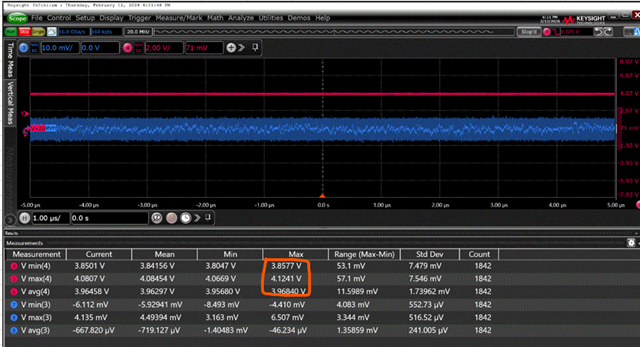
    I am a little confused with your question/results. Is the device not going to mid supply and is instead going to 4V? Not sure if that is what you are showing.

    Best Regards,

    Ignacio

  • Hi Ignacio 

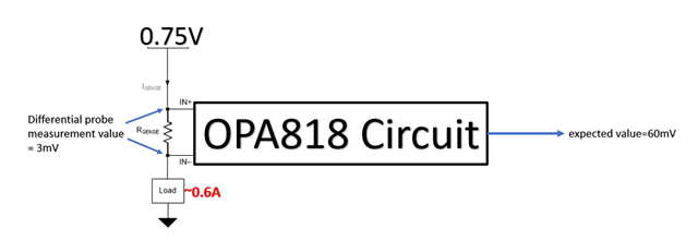
    My goal is to measure the voltage across a precision resistor (5 mΩ).

    I initially used the INA281, but found its bandwidth insufficient. Therefore, I used the OPA818 to achieve the same result.

    How can I use an external circuit + OPA818 to achieve a similar 20x amplification effect to the INA281?

    Thank you,

    Jim

  • Hi Jim,

    Can you share how you setup the OPA818EVM? Is the circuit configured the same as the circuit Sima originally created? 3mV is somewhat small of a difference for the circuit to accurately measure but it should work.

    Best Regards,

    Ignacio

  • Hi Ignacio

    Sorry for the late reply.

    1.Can you share how you setup the OPA818EVM?

    A: The environment diagram is shown below. (The circuit diagram is the same as the one recommended by SIMA.)

    Single source 12VIN to VCC ( Meanwhile VEE to ground)

    2.Is the circuit configured the same as the circuit Sima originally created?

    A. same. ( shown below)

    Power off case

    OPA818 output voltage(avg_max)=-2.13mV (default noise)

    Power on case (dc load=1A), RES use 5mohm,  Magnification: 602/2/15 = 20.0667  ,expected value(100mV)

    A. PD pin pull LOW , OPA818 output voltage(avg_max)=640mV

    B. PD pin floating ,    OPA818 output voltage(avg_max)=1.074V

    C. PD pin pull high,   OPA818 output voltage(avg_max)=1.0728V

    I have a question: What standard voltage should be connected to the PG pin?

    I'm still a bit confused about the specifications. After reading them, I think it refers to pull high.

    Thank you,

    Jim

  • Hi Jim,

    Thank you for confirming this. The concern is that the output should be at 6V (mid-supply) which it seems like it is not. The V1 DC supply in the TINA screenshot should be what sets this output. Is this bias structure setup in your design? As far as the power down pin, I believe the pin description is wrong as the device should be enabled when PD is high. To enable the device, you can float the PD pin or connect this to VS+. The EC table has these thresholds. 

    Best Regards,

    Ignacio

  • Hi Ignacio

    Q1: The V1 DC supply in the TINA screenshot should be what sets this output. Is this bias structure setup in your design?

    A:  Yes, you can understand it that way.

    I want to infer the change in current by analyzing the voltage difference between the 0V75 and the precision resistor.

    Source (Core voltage)=0V75, Rsense=5mohm , Iload=1A  ,Magnification: 602/2/15 = 20.0667

    V_offset=5m*1=5mV,  OPA818 output=100mV

    Example picture

    However, according to my actual measurements, the voltage is 0.6~1V. (expected value=0.1V)

    Q2 My goal is to measure transient current, so how should I use the OPA818?

    Thank you,

    Jim

  • Hi Jim,

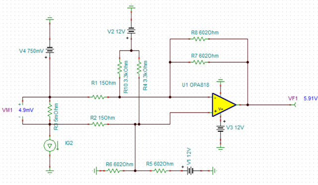
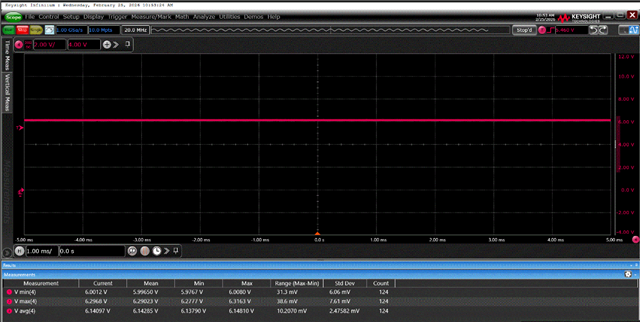
    If the device is setup how the simulation is put together you should see around ~5.9V at the output. Seeing a consistent 1V does not make much sense if the circuit is setup correctly. Are you able to probe around the circuit and see if you see the expected voltages. Even with no current through the shunt resistor, you should see 6V at the output. Another consideration is the device being stable. Could you probe the output with a scope to see if you see some kind of oscillation.

    Best Regards,

    Ignacio

  • Hi Ignacio

    Sorry, I'm a little confused.

    1.Why VM1 is 4.9mV?

    2.Why VF1 is 5.91V?

    I think so

    VM1=IG2*R3=1A*5m=5mV

    Amplifier= (620//602)/15=20.0667

    VF1=VM1*Amplifier=5mV*20.667=100.33mV

    Perhaps I am wrong, please correct me.

    Thank you,

    Jim

  • Hi Ignacio

    Based on the circuit diagram you provided, the actual test results are as follows:

    avg_max=~6.15V

    Amplifier is =6.15/0.005 =1230 ,right?

  • Hi Ignacio 

    Changing the load current: IG2 current values ​​are (0/0.6/1/2A).

    Experimental results show that the reference voltage is 6.02801V. Based on the ratio of current change to output voltage,

    approximately 1A > 100~105mV.

    Does this meet your expected design?

    Thank you,

    Jim

  • Hi Jim,

    I am attaching an article that gives a quick overview of a difference amplifier circuit and how the reference voltage takes effect on the circuits output. There is a small amount of bias current that is causing the difference voltage to not be exactly 5mV like you would expect. However, looking at your results, this is what I would expect you would see at the output for different current values. You can confirm these values by simulating the circuit for the different currents.

    Difference amplifier (subtractor) circuit (Rev. A)

    Best Regards,

    Ignacio

  • Hi Ignacio  

    Thank you for your further suggestions.

    I discovered a very interesting phenomenon. Why does the output voltage of the OPA818 change?

    I mean "Add R9 and R11" VS no "R9 and R11"

    no "R9 and R11" , OPA818 output=~6V
    "Add R9 and R11",OPA818 output=~5.56V

  • Hi,

    This is a very interesting phenomena and does not make too much sense. Considering the tolerance of the 15-ohm resistors are likely higher than the 4mohm resistors I am not sure why this big of a difference would occur. I would start by probing voltages across the sense resistor as well as the 15-ohm resistors and see what difference you see by adding the 4mohm resistors while keeping everything else the same.

    Best Regards,

    Ignacio