This thread has been locked.

If you have a related question, please click the "Ask a related question" button in the top right corner. The newly created question will be automatically linked to this question.

MPY634: Reommendation

Part Number: MPY634

Hi team, 

My customer is looking for a multipier. They want to do ouput=A²+B² equation. A and B are analog input signals. They don't need negative power supply rail and prefer to use positive only power supply. 

Do you have better recommendation?

Thanks!

Ethan Wen

  • Hi Ethan,

    Could you give more details on the application and what the range of these analog input signals are? Also, what will the power supply be? Is there a block diagram that the customer can share? 

    Thank you!
    Best regards,
    Ashley

  • Hi Ashley, 

    The input signal voltage level can be adjusted by previous amplifier. The power supply is 5V. I don't have a block diagram. This is a pre-research project, customer is sensitive to share more information. 

    Thanks!

    Ethan Wen

  • Hi Ethan, 

    At this time, we do not have a solution readily available for this transfer function. I have reached out to our design teams for assistance and will get back to you as soon as possible. 

    All the best,
    Carolina

  • Hi Ethan, 

    I have confirmed with our analog designers that we do not have this solution available. 
    To implement discretely, the following is recommended: 

    For an actual circuit that realizes output=A²+B² , things get even more complex. Putting it in terms of logarithm and exponentials, you could rewrite as such:

     A^2 + B^2 = exp [log(A^2) + log(B^2)] = exp[log(A) + log(A) + log(B) + log(B)]

     So I think we would need 5 matching diodes: 2 each to create a square of each input (logged) and then the 5th to do an antilog. Each of these diodes would have to be matched. In addition, there would be the question of what input range the customer would want.

    Here is a non-TI resource that explains the math behind the log,anti-log: Log And Anti Log Amplifiers

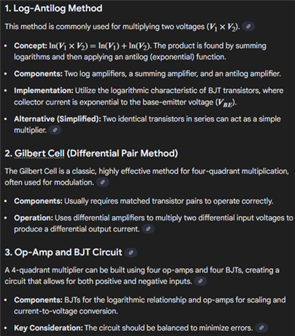
    Here are the google results: 

    If the customer requires additional help implementing discretely, I recommend posting on e2e with an op amp number. 

    All the best,
    Carolina

  • Hi Carolina, 

    Do we have simulation model for MPY634 can share with me? We have valid NDA with customer. 

    Thanks!

    Ethan Wen

  • Hi Ethan, 

    Here is the closest we have to a model of the MPY634: MPY634: MPY634 Wide Bandwidth PRECISION ANALOG MULTIPLIER - Amplifiers forum - Amplifiers - TI E2E support forums

    All the best,
    Carolina

  • Hi Carolina, 

    Thanks! 

    Could you please share the schematic symbol and PCB footprint of AD file with me? I don't find it in ti.com. 

    Ethan Wen

  • Hi Ethan, 

    Due to the age of the device, we do not have a schematic symbol or PCB footprint generated for this device. Which package are you looking for and I can try to find an equivalent device? 

    Regards,
    Ashley

  • Hi Ashley, 

    Customer would like to use SOIC package. MPY634KU. 

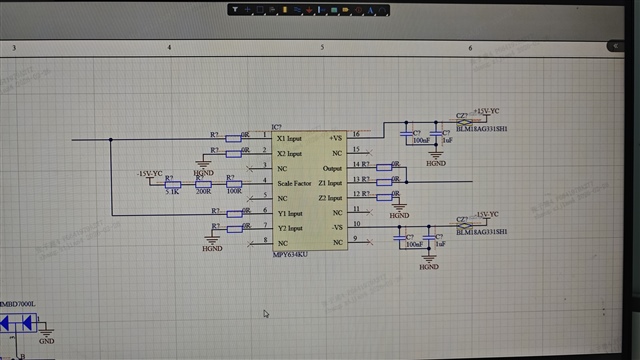
    Please help review the schematic below. SF is 5V, equation is u²/5, u is input signal. 

    Thanks!

    Ethan Wen

  • Hi Ethan, 

    The configuration of the MPY looks correct. I would recommend to make sure the input/output limits are kept within the datasheet limits. 

    We do not have the PCB footprint for the MPY device, but I have linked below the Ultra Librarian for an op amp in the same package: Ultra Librarian for TI 

    Best regards,
    Ashley

  • Hi Ashley, 

    Does MPY634 have strict requirements for the accuracy of its supply voltage? If it is powered by ±15V, but the actual supply voltage contains a ripple of ±100mV, will this affect the output results?

    Regards,
    Ashley

  • Hi Chao, 

    What is the frequency of the ripple? Unfortunately we do not have power supply rejection ratio characterized for this device, but depending on the frequency, it may introduce more noise on the output. 

    Regards,
    Ashley

  • Hi Ashley, 

    The frequency of the ripple is approximately 1.2 MHz.

    Regards,
    Chao Shen

  • Hi Chao,

    I will help support this thread while Ashley is out of office. 

    +-100mV ripple at 1.2MHz will almost certainly propagate to the output due to lack of AC PSRR. As Ashley mentioned, AC PSRR is not tested for this device. As a generalized rule of thumb, most devices will see the low frequency PSRR degrade after anywhere from .1Hz to 1kHz. Even if we assume that this device maintains the DC PSRR up to 1kHz, we would still have over 3 decades of roll-off for attenuation (less rejection characteristics).

    This device being a multiplier adds complication to the problem, as PSRR is traditionally modeled as an input referred error source relative to the IN+ terminal of the device. This ripple would likely then be subjected to any closed loop transfer function set by the MPY device. Since 1.2MHz is in the passband of the multiplier, this signal would be passed to the multiplier core. 

    What is the desired bandwidth for the multiplication of your input signals? In other words, what is your fastest input signal expected?

    Thanks,

    Jacob

  • Hi Jacob,

    Analog signals are not easily characterized by frequency. The fastest input signal is approximately 1 μs, and its amplitude is about 0.5 V.

    Regards,
    Chao Shen

  • Hey Chao,

    I see. My question regarding the frequency was to better understand if we could use large filter networks on the output to help reduce any AC PSRR errors. Since your signal is so fast, this would naturally cause excessive attenuation of your desired signal.

    I believe this is possible, but error may be excessive. 

    Input filtering before the supply lines will help remove some ripple on VCC. 

    An offset cancelation strategy can be used to help calibrate the output to help mitigate error. 

    Were you able to test the design using the MPY634 model?

    Thanks,

    Jacob

  • Hi Jacob,

    No, we haven't tested the design using the MPY634 model yet. Currently, the product is still in the design phase. We plan to use the ADI's ADP5071AREZ power chip to power the MPY634 multiplier and would appreciate your evaluation of whether the ripple voltage generated by this power chip will affect the output of the multiplier. Additionally, do you have any recommended power supply chips for the MPY634? We are open to using other chips if necessary.

    Regards,
    Chao Shen

  • Hi Chao,

    Thanks for the details. The ADP is a cool single chip split rail generator. TI does make a few parts like this, though our rail splitters do not typically go quite as high in voltage. You can always throw together an IBB plus BB to get your rails, though this requires two IC's, and a few more components. 

    All goes to say that I do not mind the converter choice, however +-100mV seeps like more ripple than the DS suggests. Is this what you guys are observing on bench? I figured we would be more in line with tens of mV of ripple worst case. 

    I cannot attach the ADI tool here, but it looks like they have a nifty calculator for evaluating the expected ripple. 

    If the ripple truly is this high, I may recommend feeding the signal into an LDO after the switching converter to help knock down the noise.  

    I am happy to help run sims with the MPY model. Are there any simulations you want to see?

    Thanks,

    Jacob