This thread has been locked.

If you have a related question, please click the "Ask a related question" button in the top right corner. The newly created question will be automatically linked to this question.

TAS6424M-Q1: TAS6424 Diagnostic

Part Number: TAS6424M-Q1
Other Parts Discussed in Thread: TAS6424

Hello.

My current diagnostic logic is as follows:

1.  Upon power-on initialization, I write 0x01 to register 0x09 to disable automatic diagnostic execution and write 0xFF to register 0x04 to manually enter diagnostic mode. Then, I read the status register 0x0F and wait until all four channels enter Hi-Z state, indicating the diagnostic has ended. After that, I read the diagnostic results from registers 0x0C and 0x0D, clear the fault, and write 0x00 to register 0x04 to set all four channels to PLAY mode. The results obtained from the power-on diagnostic are accurate.

2.  During operation, I continuously monitor the FAULT pin level. When a fault is detected (i.e., the FAULT pin is pulled low), I read status register 0x0F to identify the faulty channel(s) and manually send a diagnostic command to the faulty channel by writing to register 0x04 to put it into diagnostic mode. (For example, if register 0x0F shows channels 1, 2, and 3 in PLAY mode and channel 4 in Hi-Z, this indicates a fault in channel 4. In this case, I write 0x03 to register 0x04 to manually send a diagnostic command for channel 4.) Then after 1s, I read the diagnostic results from registers 0x0C and 0x0D. However, the diagnostic results for the faulty channel keep fluctuating at this stage.

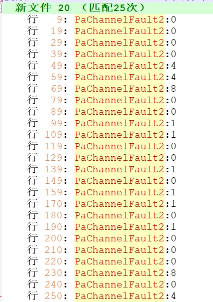
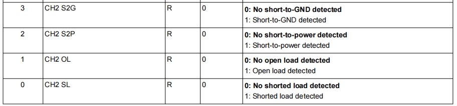
    For instance, as shown in the diagram, when channel 2 is shorted to ground, `PaChannelFault2` (the 4-bit value read from the register representing the corresponding channel) fluctuates continuously between no fault, short to ground, short to power supply, and short circuit.


I would like to know what might be wrong with my current real-time diagnostic logic. Could you also provide a detailed, correct real-time diagnostic procedure?1.jpg2.jpg3.jpg4.jpg
  • Hi Ive,

    Could you clarify what the first picture is trying to show?

    After that, I read the diagnostic results from registers 0x0C and 0x0D, clear the fault, and write 0x00 to register 0x04 to set all four channels to PLAY mode.

    When you mention that you "clear the fault" here, what faults are you clearing?

    When a fault is detected (i.e., the FAULT pin is pulled low),

    Did you read what FAULT this is? I'm assuming OC, is that correct?

    2.  During operation, I continuously monitor the FAULT pin level. When a fault is detected (i.e., the FAULT pin is pulled low), I read status register 0x0F to identify the faulty channel(s) and manually send a diagnostic command to the faulty channel by writing to register 0x04 to put it into diagnostic mode. (For example, if register 0x0F shows channels 1, 2, and 3 in PLAY mode and channel 4 in Hi-Z, this indicates a fault in channel 4. In this case, I write 0x03 to register 0x04 to manually send a diagnostic command for channel 4.) Then after 1s, I read the diagnostic results from registers 0x0C and 0x0D. However, the diagnostic results for the faulty channel keep fluctuating at this stage.

    The process looks good to me, can you send me a record of all the reads and writes in this step?

    Elise

  • Hello Elise, sorry for the late reply due to the Chinese Lunar New Year holiday.

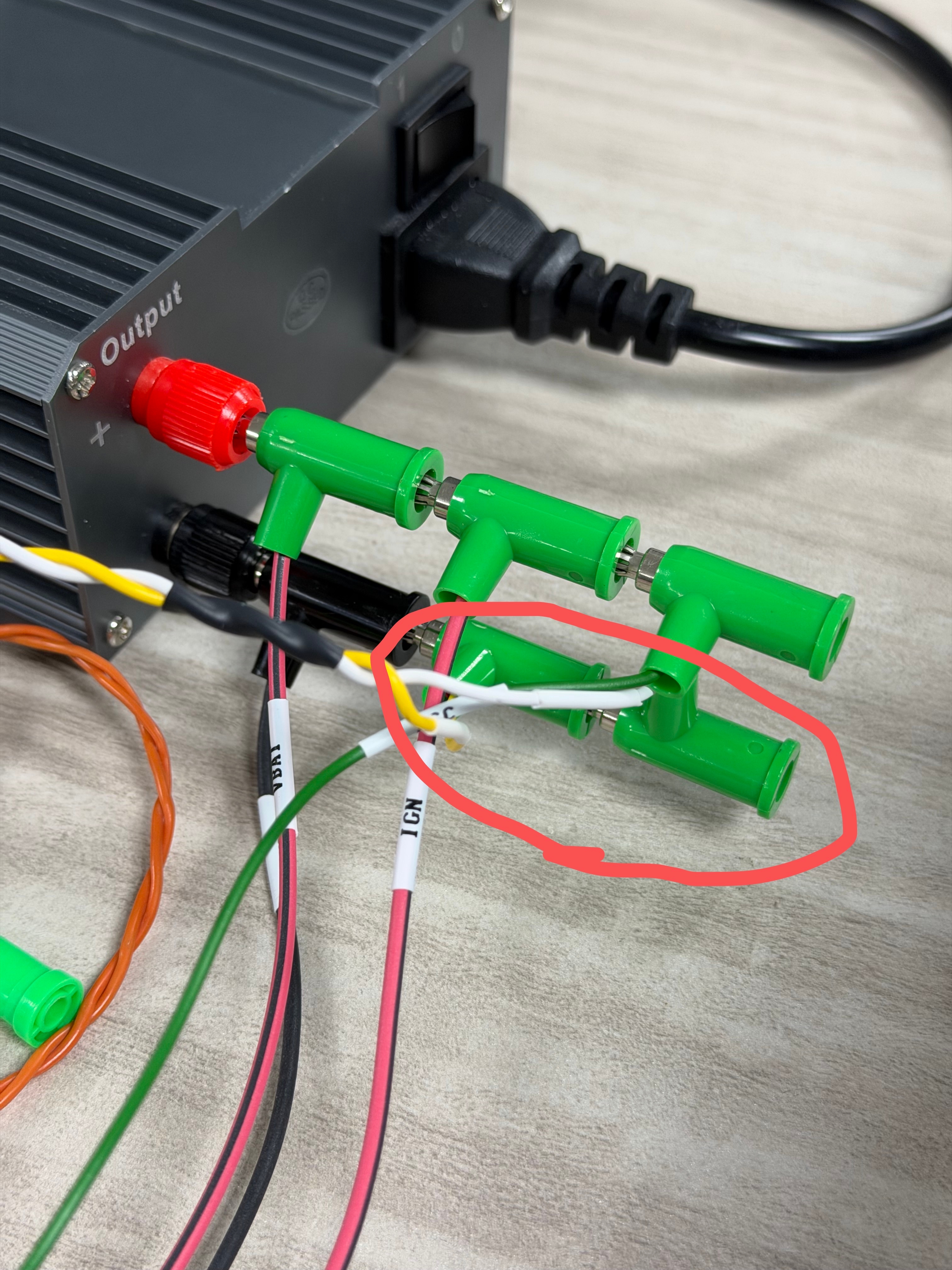
    1. I want to show you my method for creating a fault. Within the red circle in the image are the positive and negative output terminals of the AMP. I create a short-to-ground fault by connecting them together and then to the power supply ground. Based on the response I reviewed at this link: TAS6424-Q1: DC diag: Can OL/SL and S2P/S2G happen simultaneously? - Audio forum - Audio - TI E2E support forums, only S2G will be detected in this state.

    2. I clear the fault by writing 0x80 to register 0x21, which sets the CLEAR FAULT bit to 1 (meaning "Clear fault").

    3. Yes, it is indeed observable in the 0x10 register that the faulty channel is in an OC state.

    4. The following is a part of records of reading and writing registers during real-time DC diagnostics. The faulty channel in this process is CH1 shorted to ground. Each cycle begins with "FAULT PIN IS LOW". Since the faulty channel is CH1, the specific fault type should be read from the upper 4 bits of the 0xC register. You can see that the upper 4 bits of the 0xC register are constantly changing.
    [16:54:19.880]收←◆FAULT PIN IS LOW
    READ REG:0xf, Data:0x40
    WRITE REG:0x4, Data:0xc0

    [16:54:21.900]收←◆READ REG:0xc, Data:0x40
    READ REG:0xd, Data:0x22
    WRITE REG:0x21, Data:0x80
    WRITE REG:0x4, Data:0x0

    [16:54:22.922]收←◆FAULT PIN IS LOW
    READ REG:0xf, Data:0x40
    WRITE REG:0x4, Data:0xc0

    [16:54:24.925]收←◆READ REG:0xc, Data:0x80
    READ REG:0xd, Data:0x22
    WRITE REG:0x21, Data:0x80
    WRITE REG:0x4, Data:0x0

    [16:54:25.953]收←◆FAULT PIN IS LOW
    READ REG:0xf, Data:0x40
    WRITE REG:0x4, Data:0xc0

    [16:54:27.956]收←◆READ REG:0xc, Data:0x10
    READ REG:0xd, Data:0x22
    WRITE REG:0x21, Data:0x80
    WRITE REG:0x4, Data:0x0

    [16:54:28.957]收←◆FAULT PIN IS LOW
    READ REG:0xf, Data:0x40
    WRITE REG:0x4, Data:0xc0

    [16:54:30.961]收←◆READ REG:0xc, Data:0x90
    READ REG:0xd, Data:0x22
    WRITE REG:0x21, Data:0x80
    WRITE REG:0x4, Data:0x0

    [16:54:31.995]收←◆FAULT PIN IS LOW
    READ REG:0xf, Data:0x40
    WRITE REG:0x4, Data:0xc0

    [16:54:34.003]收←◆READ REG:0xc, Data:0xd0
    READ REG:0xd, Data:0x22
    WRITE REG:0x21, Data:0x80
    WRITE REG:0x4, Data:0x0

    [16:54:35.036]收←◆FAULT PIN IS LOW
    READ REG:0xf, Data:0x40
    WRITE REG:0x4, Data:0xc0

    [16:54:37.043]收←◆READ REG:0xc, Data:0xd0
    READ REG:0xd, Data:0x22
    WRITE REG:0x21, Data:0x80
    WRITE REG:0x4, Data:0x0

    [16:54:38.058]收←◆FAULT PIN IS LOW
    READ REG:0xf, Data:0x40
    WRITE REG:0x4, Data:0xc0

    [16:54:40.070]收←◆READ REG:0xc, Data:0x90
    READ REG:0xd, Data:0x22
    WRITE REG:0x21, Data:0x80
    WRITE REG:0x4, Data:0x0

    [16:54:41.094]收←◆FAULT PIN IS LOW
    READ REG:0xf, Data:0x40
    WRITE REG:0x4, Data:0xc0

    [16:54:43.096]收←◆READ REG:0xc, Data:0xd0
    READ REG:0xd, Data:0x22
    WRITE REG:0x21, Data:0x80
    WRITE REG:0x4, Data:0x0

    [16:54:44.129]收←◆FAULT PIN IS LOW
    READ REG:0xf, Data:0x40
    WRITE REG:0x4, Data:0xc0

    [16:54:46.133]收←◆READ REG:0xc, Data:0x50
    READ REG:0xd, Data:0x22
    WRITE REG:0x21, Data:0x80
    WRITE REG:0x4, Data:0x0

  • Hi Ive

    I create a short-to-ground fault by connecting them together and then to the power supply ground.

    So the situation you created, is OUTP short to OUTM, also they are both Shorted to GND. This is a double fault, device will detect the fault, but can't guarantee which one to report.

    Kindly have a try, to only short OUTP and OUTM. Or only short 1 of the OUT to GND. The results would be much more stable.

  • Hello Shadow, the short to ground fault mentioned in the previous answer was caused by shorting only 1 of the OUT to ground, but the diagnosis result still shows instability as indicated in the register above.

  • Hi Ive

    Seems the CH2 always in PLAY mode, it's possible that crosstalk affected the DC diag results.

    Kindly have a try with below sequence.

    When OC been triggered on CH1.

    Set reg 0x04 with value 0x55, to put device in HiZ state.

    Set reg 0x21 with value 0x80, to clear fault.

    Set reg  0x04 with value 0xff to do DC diag.

    Check the results.

  • Hi Shadow

    Thanks for your reply. I performed the diagnostics in the order you suggested, and the results are currently stable. Thank you again!

    However, I still have a few questions:
    1. Based on what you mentioned, CH2 being in playback mode affected the diagnostic results of CH1. I would like to understand the specific channel interaction. For example, do only CH1 and CH2 affect each other, and similarly CH3 and CH4 affect each other? Or does the diagnostic result of each individual channel get influenced by the other three channels?
    2. Our goal is to perform real-time diagnostics without affecting sound playback when the ECU is functioning normally. However, in the current process, when the FAULT pin is detected as low (indicating at least one channel has a fault), all four channels are first switched to Hi-Z mode, and then all four channels enter diagnostic mode simultaneously. This disrupts the playback of channels that are functioning normally. Is there a way to perform diagnostics without affecting the channels that are playing normally?

  • Hi Ive

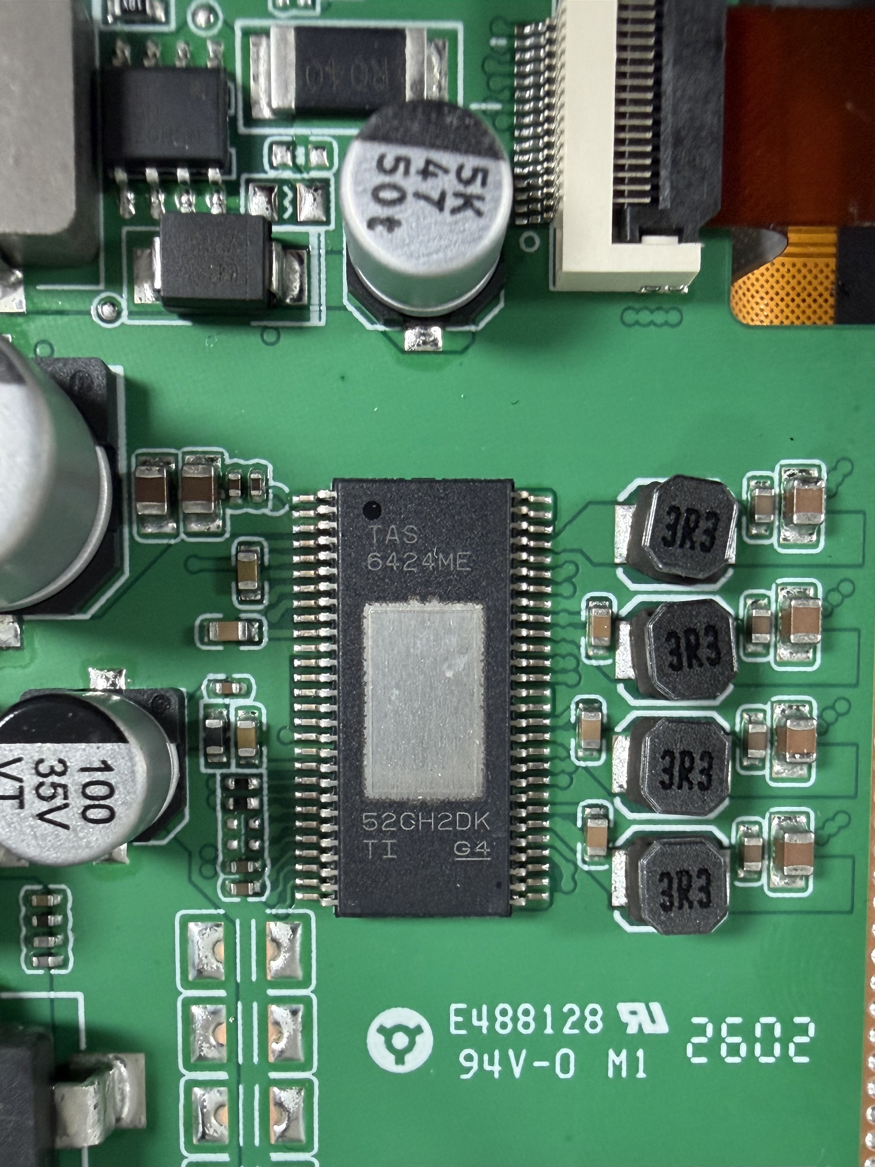
    The cross talk energy mostly coming from the inductor on the PCB. And usually the adjacent channel would be affected. 

    For your board, could have a try with shielded inductor first. Right now the ferrite inductor you used has the worst cross talk performance. If still not good enough, may have to put inductors more far away with each other.

  • Hi Shadow.

    Regarding the diagnostic issue we consulted about earlier, since the project is already in its late stages, hardware modifications are very difficult. With the customer's approval, we will only perform power-on diagnostics and not real-time diagnostics.

    However, we have encountered another issue during testing: when a channel experiences a fault during playback (such as a short to ground), the channel does not automatically return to PLAY mode to resume playback after the fault is removed. I would like to know if the TAS6424 chip can recover automatically, or if manual recovery via software is required? If manual software recovery is needed, could you provide the specific operating procedure? Thank you!

  • Hi Ive

    Most of the fault won't able to auto recover. Because IC itself can't know if the external fault scenario been removed or not. If the shortage still exist, but IC try to keep recover, it would be dangerous.

    Needs you to remove external fault condition first, then set "Clear Fault" in register 0x21.