This thread has been locked.

If you have a related question, please click the "Ask a related question" button in the top right corner. The newly created question will be automatically linked to this question.

INA181: Time delay in output

Part Number: INA181

I am trying to simulate a circuit with an INA181 current sense IC. 

I have boiled it down to this circuit:
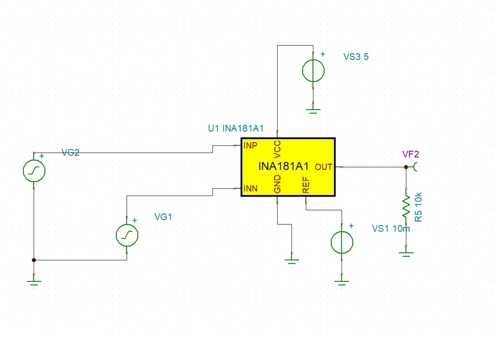
ckt.jpg

And I just pulled the spice model today.

When Vs1 is 0V (i.e., shorted to ground) I get this:
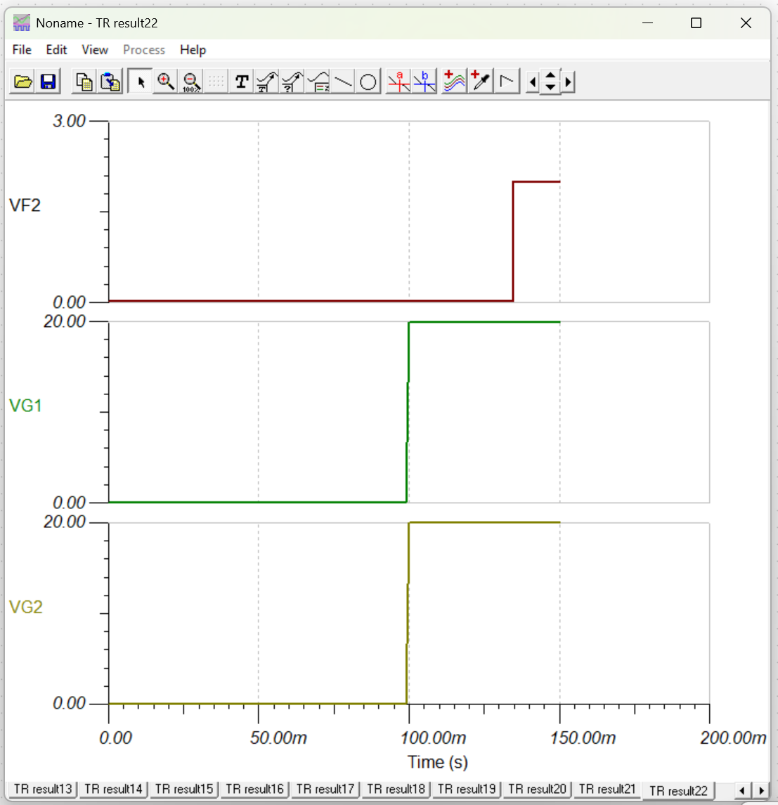
image.png

Note the time delay in the output, VF2. By adding a 50mV offset to Vs1, we get this:
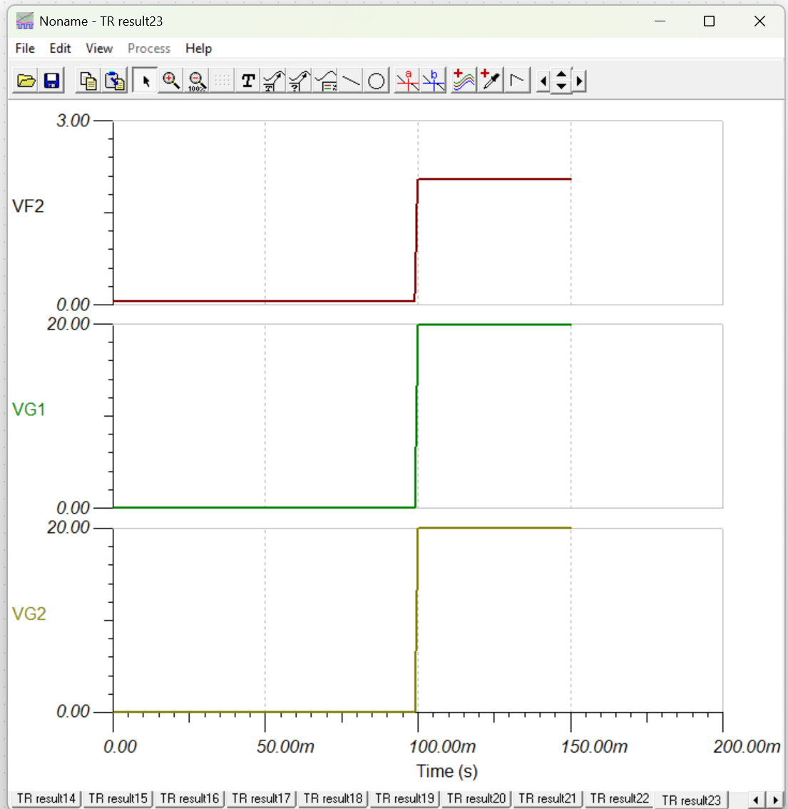
image.png

Where everything lines up nicely.

I assume this has to do with:

"The linear range of the output stage is limited by how close the output voltage can approach ground under zero input conditions. In unidirectional applications where measuring very low input currents is desirable, bias the REF pin to a convenient value above 50 mV to get the output into the linear range of the device." from 7.4.2 of the data sheet, but I see nothing about how long it takes to recover from non-linear to linear range. 25 ms seems a bit excessive.

So is this just a SPICE artifact or actual device behaviour. Is there anyway to correct this without putting a voltage on the ref pin?

  • Keith, 

    You've pretty much nailed this on the head. Any amplifier will saturate if it is driven outside of its linear operation area, ie, "railing" the device. As per the INA181 datasheet, the ability of the device to swing to GND is typically around 0.5mV above GND, with a worst case of 5mV above GND (for a 10kΩ load condition. Figure 6-19 shows other loading conditions and the devices ability to swing):

    In regards to the question, "So is this just a SPICE artifact or actual device behaviour," the answer, technically, is both. Saturation is a non-linear operation, and is incredibly difficult to model accurately (and even models that attempt to do this will typically only do so for a single point). Various factors of how far the amp is driven into saturation, how quickly its brought out, etc. can all have bearing. So, in short, yes, the behavior the PSPICE model is showing you is real, but I agree with you that the 25ms the model is showing is excessive. Most amplifiers will bring themselves out of saturation within a few microseconds, although it may be longer. Its just not modeled. 

    Finally, unfortunately there is not a way to avoid this other than keeping the amplifier in the linear range. Can you share a bit about what you are looking to measure here and what you are trying to achieve? I could help brainstorm if that is of value here. 

  • Thanks, It is for a data acquisition system with telemetry. We are just getting started, so I am not sure exactly what we will be able to do. We are measuring the current through a fuse (not really, but close enough). So it will sit at 0 V for a long time, rise to some current when the voltage is applied but before the fuse blows, and then go back to zero once the fuse opens.

    I know we used a INA181 previously, so I am going to look back and see how they handled it. (If they did!)

    Do you know of another chip that might work better when left at zero for a while?

  • Keith, 

    For this use case, I dont really have any additional recommendations if the INA181 looks to do the job here. Any device is going to exhibit a saturation recovery effect if it is saturated into the rail prior to measuring current. The only potential workaround I could recommend if you are trying to avoid additional circuitry to set a reference is to use something along the lines of the INA296, where you can set the reference via VS and GND only, which would set the device at mid-supply, and then you could dial in your sense resistor network from there. The tradeoff though is that you would be giving away a decent chunk of your full scale range to do this.