This thread has been locked.

If you have a related question, please click the "Ask a related question" button in the top right corner. The newly created question will be automatically linked to this question.

LM358: LM358D failing to modulate gas valve

Part Number: LM358
Other Parts Discussed in Thread: LM317

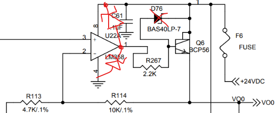
I work for a company that uses the LM358D to modulate a 0-10V (control signal) modulate gas valve (power is 24VAC). The after a random amount of time, the LM358D will only output ~10V and will not drop to ~0V. We send a 0-3.3V signal to the LM358D from a DAC (DAC128S085CIMT/NOPB) which tells to LM358D to output 0-10V. The circuit is seen in the image below. 

image.png

We use 75,000 (3 per PCB) of the LM358 annually and only see this issue on about 10% of boards. There is two gas valve circuits, and one or the other breaks in that 10% of boards. 

The gas valve we use it the E61 from Maxitrol: https://www.maxitrol.com/exa-modulation/

We were hoping to get some technical consulting to what might be causing this chip to fail since the datasheet states 2kV of ESD protection. Future revisions of the board we have added a baker clamp and simulation proved that works to prevent large transient spikes of voltage(+/-67V) and current(15A).


Any help would be greatly appreciated! 


  • Hi Austin,

    It seems the device suffers some sort of electrical over-stress behavior.  We have some training for electrical overstress at the following location:

    https://www.ti.com/video/series/precision-labs/ti-precision-labs-op-amps.html

    Look for Electrical Overstress (EOL).  Generally we recommend TVS diodes on the supplies and resistors on the inputs.

    In this case it may related to the output.  EOS is common in low impedance circuits connected to the output of the amplifier because it is easier to generate an excessively high current.  This was my immediate suspicion, assuming the node you have labeled as "GAS VALVE" is low impedance.  However if I look at the data sheet for that valve, it says the input impedance is 100 kOhm.  This does not make sense that you would have a fuse and higher power bjt to drive a 100kOhm input impedance.

    Can you give more information about the node that says "GAS VALVE"?  Specifically what is the impedance, and, how is it grounded?  Is it possible the ground for "GAS VALVE" is a much different voltage than the ground for LM358?

    Regards,
    Mike

  • Hi Michael,

    Thank you for your help! I will watch those videos. In our future revision we were going to add a TVS diode on the output like so: 

    (VO0 is going to the gas valve)

    The gas valve data sheet states that the input impedance is 50k ohms. So, I agree that it does not make sense to have a such a high power BJT. (Note: this circuit was not designed by me. I just started at this company and I picking up where the previous engineer left off.) Do you think it would be worth changing the BJT to a lower power BJT so there's not as much drive? 

    The gas valve is powered by a 120VAC to a 24VAC (20VA) step down transformer. So, there a hot and neutral wire to and from the the gas valve. The LM358 is a DC ground meaning that there is no continuity between the power of the gas valve and the control signal/LM358 ground. The LM358 ground and the control signal ground are connected on the ground plane of the PCB. 

    Let me know if you need any more information!

    Thank you so much for your help!

    Austin

  • Hi Austin,

    Yes the TVS on the output is a good idea.  You'll see from the training that we also recommend a TVS on the power supply (24 V in this case) .  The reason is that if an excessively high voltage gets exposed to the device, current can flow through the amplifier's ESD cell, and back into the supply.  Some supplies cannot sink current, so, then the supply voltage increases, potentially to a failing point.  How is the 24V created?

    The ground must be connected somehow from the valve to the amplifier, as I understand it the valve would reference the same ground.  But, my main concern was more that the load would be a low impedance (the load connected to node VO0); if there were ground differences then high current could be conducted back into the circuit but it seems this is not the case.

    Also, the Schottky diode can always help, but would be better on the amplifier side of the resistor at the base of the bjt.  Here's our recommendation:


    The Schottky will conduct current that may be forced from an external source back to the supply or GND, instead of back through the amplifier.  This is a common recommendation for power amplifiers where the load can have large transients that will conduct back into the amplifier.  I must admit I'm not sure how this could happen here back through the bjt, but this would assure a high level of robustness.

    Lastly, there is no resistor from the DAC to the amp.  Resistors on the inputs always help limit current flow in the case that the input can have a high voltage excursion. I don't think this would happen with the DAC, but it couldn't hurt. 

    So, without any information about where the transients may come from or why this issue occurs, if you take all of these into account that should give a fairly robust solution.

    Hopefully this helps.

    Regards,
    Mike

  • Hi Michael,

    I will give that a shot. It takes a couple months for prototypes so I may follow up at a later date.

    Here is how we are getting +24VDC for reference. The 24VAC is from a 120VAC to 24VAC transformer off board. 

    Thank you so much for your help!!

    Austin

  • Hi Austin,

    Ok got it.  Yes the classic LM317 has no ability to sink current.  So, if you could imagine that you forced current back INTO the 24 V node, as soon as you exceeded the quiescent current of the load on the 24 V node, then any additional current will cause that 24 V to rise up, because LM317 cannot sink it to ground.  Additional current will cause the 24 V to rise up to the input voltage of LM317, at which point I believe it will back-conduct into the 24 VAC node.  Even then, I assume your 24VAC (VAC would have to be DC, not AC, the input of LM317 can't go below GND) is a basic rectified voltage, which means there are just diodes to the transformer, they also will block any reverse current flow.  Then the input voltage will rise as well.

    Long story short, if you can add a TVS to the 24 V node, you will give a path to ground for a transient surge that otherwise may cause your 24 V to turn into a much higher voltage, then causing the amplifier to get exposed to a supply voltage above its abs. max. voltage.

    Let me know when you get get some updates.

    Regards,
    Mike