This thread has been locked.

If you have a related question, please click the "Ask a related question" button in the top right corner. The newly created question will be automatically linked to this question.

OPA2182: It takes six hours for the output to stabilize.

Part Number: OPA2182
Other Parts Discussed in Thread: OPA182

Dear Speciists,

My customer is evaluating OPA2182 and encountering offset drift issue.

I would be grateful if you could advise.

---

A differential amplifier was configured using an OPA2182 and the voltage was measured at the output pin.
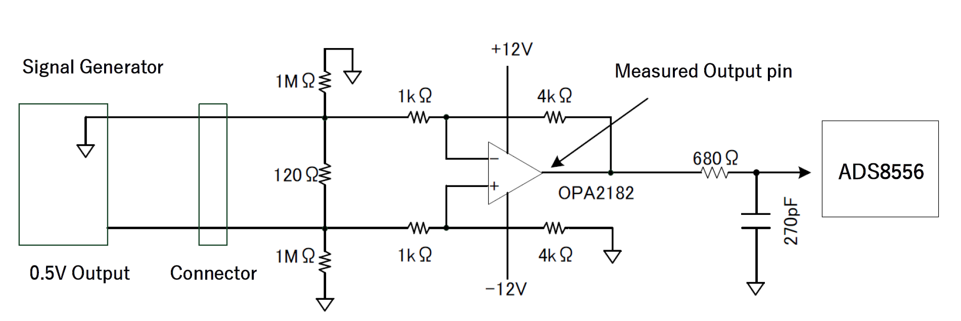
image.png


The board and voltage generator were powered on (the voltage generator output was OFF at this time), and after about two hours, 0.5V was output from the voltage generator and measurements began.
It took nearly six hours for the op amp's output to stabilize.
This is considered an impossible phenomenon under normal circumstances.
Data was collected once per minute and graphed.
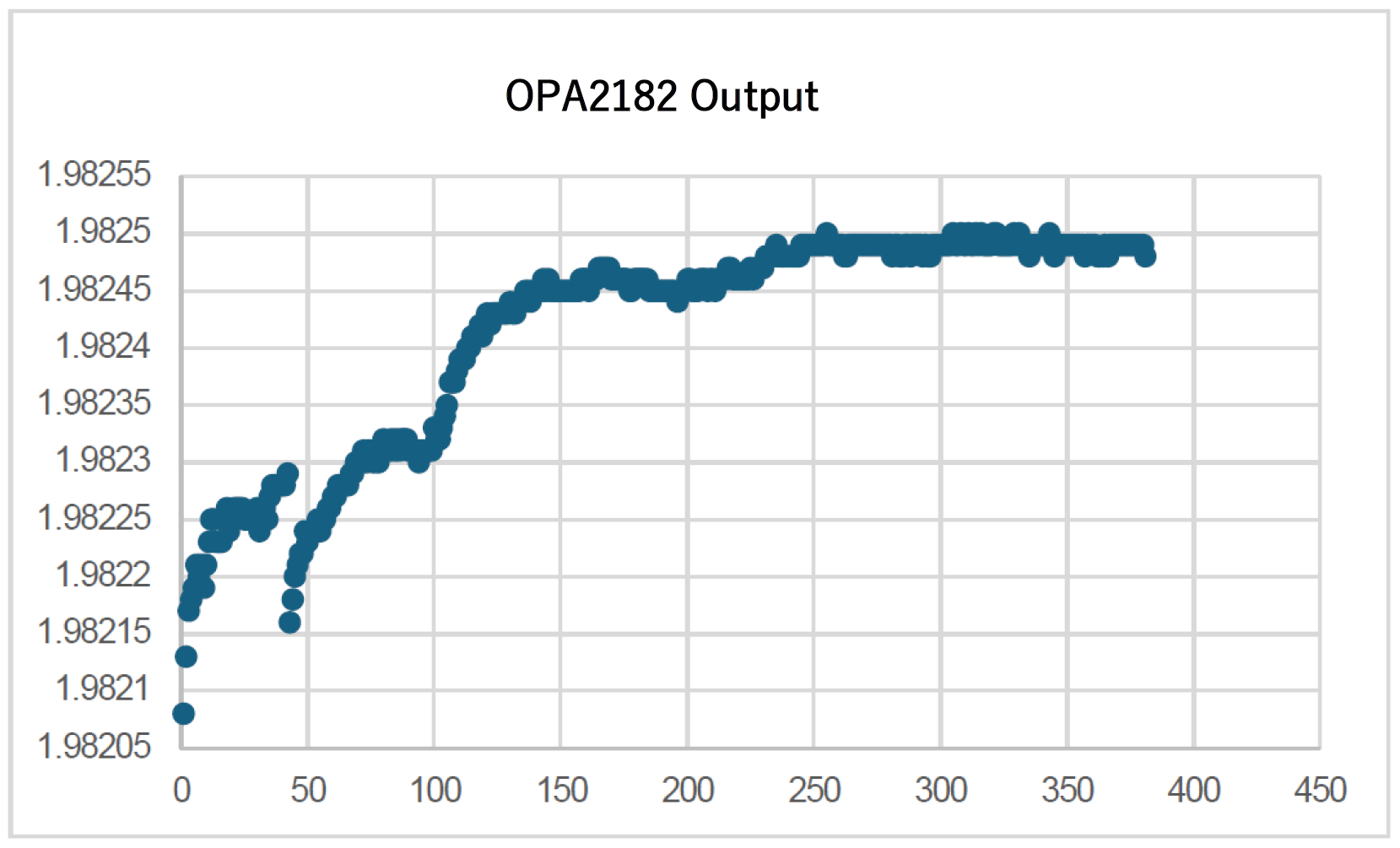
image.png

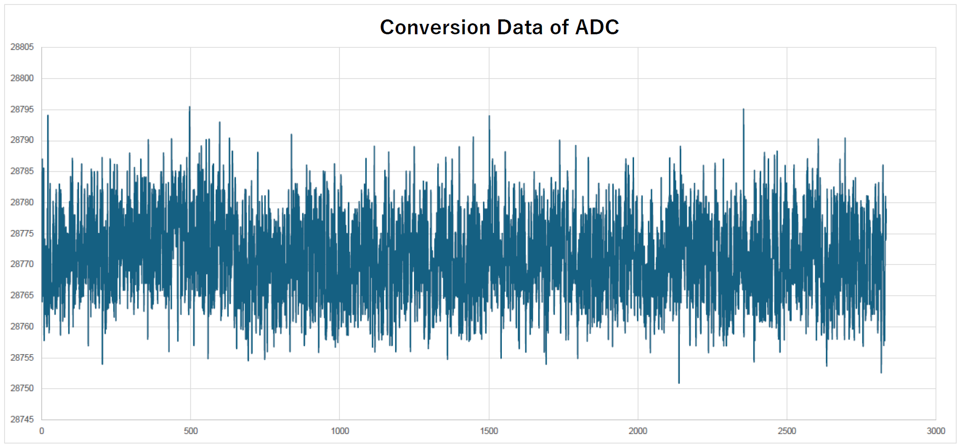
When the AD conversion value is also collected every 20 seconds, the graph shown below appears.
Even ignoring subjective noise, the changes in the values ​​are quite unstable.

image.png

Could you please let me know the cause and solution.

Question about OPA2182 Offset Drift .pdf 

---

I appreciate your great help in advance.

Best regards,

Shinichi 

  • Shinichi,

    1. I checked "loop stability" for your design.  The term "stability" with op amps often refers to loop stability.  Something that is not stable from a loop-stability perspective will oscillate due to a capacitive load.  Your circuit does have a capacitive load but the circuit is very stable from a loop (phase margin) perspective.
    2. I looked at noise for your circuit.  Op amps and resistors generate noise.  The OPA2182 has an input noise density of about 5.7nV/rtHz.  This noise density will integrate across frequency to a total RMS noise of 33.9uV RMS. 
      1. To convert RMS to peak-to-peak you multiply by 6.  Thus, according to simulation this circuit should have 203uVpp. 
      2. I do not know what your analog-to-digital converter LSB is set to.  I need to know the LSB to convert the codes in the time domain graph to a peak-to-peak voltage level. 
      3. Your time plot does look like white random noise (i.e. not drifting).  This may just be because a short time interval was looked at or because it was captured when the circuit was no longer drifting (after the 6 hours).  I do see a little bump at around 500 counts, but otherwise this looks Gaussian and random (i.e. noise).  You mention "Even ignoring subjective noise, the changes in the values ​​are quite unstable".  This video series covers noise:  https://www.youtube.com/watch?v=ewArZEGlLWw&list=PLISmVLHAZbTTDLx9fFteXntj2zsJqVRvN . Here is a short article on the subject:  https://www.edn.com/intrinsic-op-amp-noise-in-a-nut-shell/ .  I am not saying that the circuit doesn't have a problem, but the signal does look like a random gaussian noise.
    3. The OPA182 is a very low drift part.  Your excel graph that shows the drift changes about 400uV across the 6 hr time span.  I would not expect an OPA182 to drift anywhere near this much.  The main thing that causes drift is temperature change.  You did not mention the temperature change across the 6 hrs, but I assume that it is just ambient temperature variation.  Really, the OPA182 should drift about 0.02uV/C MAX, so for ambient temperature variation you shouldn't even see 1uV of change.  The gain of your circuit will drift due to the temperature coefficient of the resistors (nothing to do with the op amp).  However, even 1%, 100ppm/C resistors shouldn't cause this much drift for ambient temperature variation.
    4. Possible issues:
      1. Probably the most likely reason the output is drifting is the input signal.  The output signal is dependent on the 0.5V input and the signal generator input.  In general most signal generators are designed to output moderate fidelity signals, but not precision low drift DC offsets.  You should check your signal generator output directly with a precision digital multimeter and check to see if your input signal is drifting.
      2. Another possibility is that this is just the op amp noise.  I don't think this is the case because your excel graph looks like it shows a significant drift.  Your time domain graph (20 seconds) mostly looks like noise, but I think this is just because 20 seconds isn't long enough to see the drift happen.
      3. If you have a very precise DC source or a precise voltage reference connected to the input, I don't think you would see the drift.

    Best regards, Art

  • Hi Art,

    Thank you for your reply.

    I understand that the signal generator output is the most likely cause.

    I shared this information with the customer and confirm.

    When the customer has an additional question, I consult you again.

    I appreciate your great help and cooperation.

    Best regards,

    Shinichi

  • Shinichi,

    We'll close this thread for now but you can re-post to open back up when you get more information.

    Regards,
    Mike

  • Hi Mike,

    thank you for your reply.

    I agree.

    When the customer has an additional question, I'll ask from new thread.

    I appreciate your great help and cooperation.

    Best regards,

    Shinichi