OPA2810: Phantom Current - Differential amplifier configuration

Part Number: OPA2810
Other Parts Discussed in Thread: LMV611

Hi, im using OPA2810IDGKR as differential current sense amplifier in my sawtooth wave generation design.

OPA2810IDGKR.jpg

I have attached the circuit of the same. Here the U11 opamp power is changed from 3.3V to 15V.

While doing the current measurement during testing, i have found Phantom Current on the output of the differential amplifier opamp U11 which is given below.

image.png

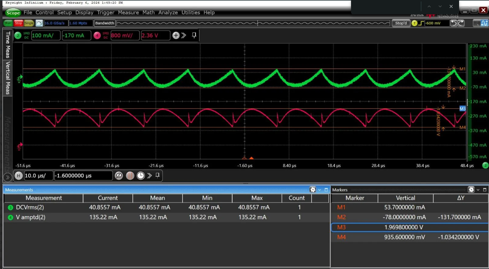
Here the green waveform represents the current passing through the load which is a coil of 220uH inductance and 50 ohms DC resistance connected across P1 and P2 measured using current probe.

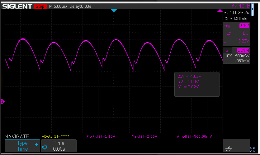
The red waveform represents the output of U11A. To reduce the Phantom Current, i have changed the resistors R51 & R54 to 100E and R50 & R55 to 10K with 1% tolerance and i got good improvements which is given below.

image.png

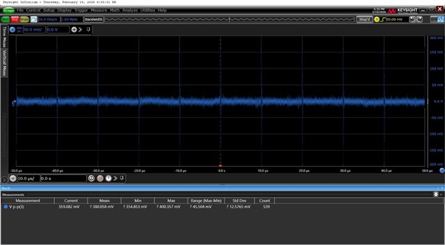
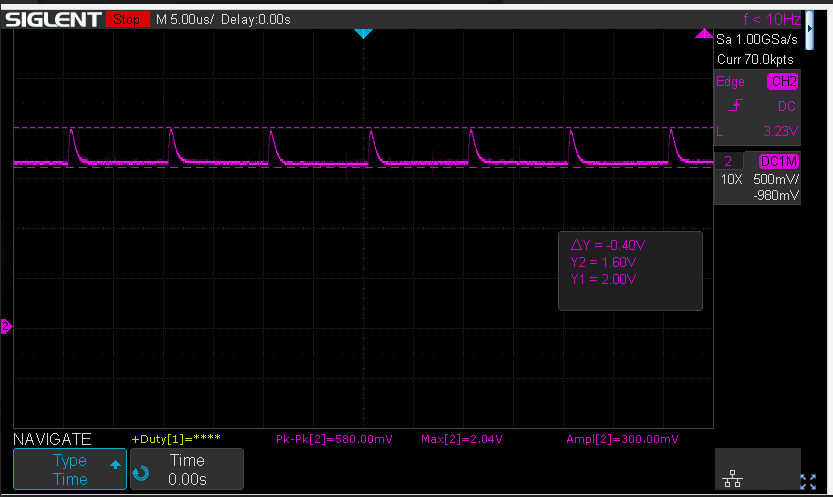
The phantom current is still present in the output of U11A and it is reflecting during no load condition also. I have captured the output in no load condition below.

image.png

Could you please suggest how I can completely eliminate the phantom current from the output of the differential amplifier U11A. 

  • Hi,

    Could you explain what you mean when you mentioned during no load condition you still see something at the output of the OPA2810? Does this mean you are floating the inputs (ICOIL IN+ and ICOIL IN-)? If so, could you confirm if the output is at the expected level of 7.5V it is hard to tell in your screenshots. If the circuit is at the expected voltage is the issue you are seeing similar to the last screenshot you attached? I captured the circuit in simulation, and the circuit does what is expected so I am curious if maybe the circuit being implemented is causing issues. Confirming you do see 7.5V at the output would be a good start.

    Best Regards,

    Ignacio

  • Hi Ignacio,

    The circuit is essentially a sawtooth wave generator. By default, the waveform is continuously generated and then amplified to the required level of 20Vpp using the U12 op-amp, as shown below.

    When an inductive load is connected across the P1 and P2 terminals, I can observe the expected current flow, as shown in the attached waveform.

    Therefore, irrespective of whether a load is connected or not, the sawtooth waveform is always present. The current-sense differential amplifier feedback path is used to measure the current through the inductive load and adjust the sawtooth voltage whenever the current crosses the defined threshold.

    The issue I am facing is that, in both loaded and no-load conditions, I am observing a phantom current during the falling edge of the sawtooth waveform. I would like to completely eliminate this behavior.

    I hope this clarifies the basic operation of the circuit. Please feel free to reach out if any additional details are required.

    Thanks & regards,
    Jitheesh

  • Hi Jitheesh,

    Thank you for the additional details. I would like to confirm you are connecting the inputs to your difference amplifier U11A to P1 and P2. If so, even when you're not connecting a load, from what I understand you are still driving P1 and P2 correct? In that case you would see this saw tooth signal across the inputs of your difference amplifier. Are you seeing the difference amplifier rail out or something along those lines? Could you probe the inputs? (ICOIL_IN+ and ICOIL_IN-)

    Best Regards,

    Ignacio

  • Hi Ignacio.

    Please find the waveform taken across sense resistor (ICOIL_IN+ and ICOIL_IN-) without load given below.

    Please find the waveform taken across sense resistor (ICOIL_IN+ and ICOIL_IN-) with load given below.

    Thanks & regards,
    Jitheesh

  • Hi,

    Thank you for sharing these. It does make sense that you are seeing this across the sense resistor. With this same condition I assume you are seeing the pink signals from your original post at the output of the difference amplifier. You did add that you later increased the supplies to the OPA2810 from 3.3V to 15V. This is the correct step as 3.3V is below the minimum recommended supply for this device. However, the reference buffer (LMV611) you are using has a max supply of 5.5V and from your schematic, you are sharing the same supply with the OPA2810. Could we confirm if this is the case? I am trying to focus on the difference amplifier now that we know the input signal should be ~0V from your screenshots.

    Best Regards,

    Ignacio

  • Hi Ignacio,

    You are correct, I can confirm that the supplies are given as you mentioned.

    Thanks & Regards,

    Jitheesh 

  • Hi Jitheesh,

    I am wondering now if you are getting some of these errors due to the voltage supply of the LMV611 being too high and potentially leading to internal damage if this was set to 15V. Could you try setting the voltage to 5V? This would be just enough for our OPA2810 and is within the upper limit of the LMV611.

    Best Regards,

    Ignacio

  • Hi Ignacio,

    I believe my previous response may have caused some confusion.

    The LMV611 (U10) is powered solely from the 3.3V supply. Only the U11A (OPA2810) supply was isolated and changed from 3.3V to 15V. The LMV611 and OPA2810 do not share the same power supply.

    Therefore, the issue is not related to the LMV611 supply.

    Please let me know if any further clarification is required.

    Thanks & Regards,
    Jitheesh

  • Hi Jitheesh,

    Sorry for the misunderstanding on my side in that case this is not an issue. I was looking at the screenshot of ICOIL_IN+ and ICOIL_IN- and it does look like there is some kind of spike at 10us and is repeated. Is this accurate, if so, this should result in some output at the difference amplifier.

    Best Regards,

    Ignacio

  • Hi Ignacio,

    Yes the spikes in the input at 10us intervals are causing the spikes at the output also. So, could you please suggest some solutions or workarounds that can be implemented to suppress those spikes without affecting the main input signals. The main input will be in the semi parabolic shapes reapeating at 10us intervals without spikes.

    Thanks & Regards,

    Jitheesh 

  • Hi Jitheesh,

    I was wondering if you could probe around the circuit feeding the two connectors (P1 and P2) and see where this spike is coming from. I would probe the very input before and after the AC capacitor as well as the output connected to P2. 

    Best Regards,

    Ignacio