This thread has been locked.

If you have a related question, please click the "Ask a related question" button in the top right corner. The newly created question will be automatically linked to this question.

LMP7721: Capacitance Problem when is power on first time has problenm second wotrks correct

Part Number: LMP7721
Other Parts Discussed in Thread: ADS1255, TINA-TI

We use LMP7721 and AD1255 

The issue when is poer on the first time the ADS1255 read woprng values when is power OFF and ON the system work well

Our Application is for TIA , the photocell capacitancre is 200 pF

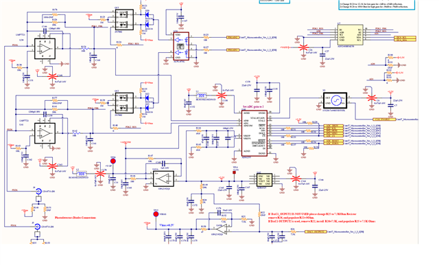
Could please tell me C146 =1200 pF and R128 =10 Ohms and C148 =0.1uF are the problem the changing the capacitance provoquin the ADS1255 read wrong values

Could you suggest and values

Regards

ATLMP7721.png
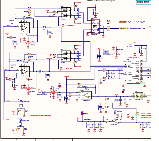
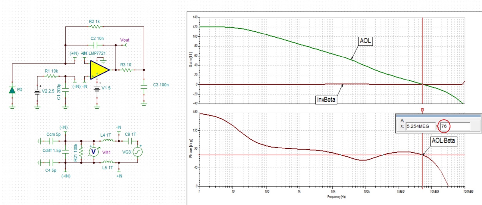
  • It's impossible to read your schematic but I had made some assumption regarding the circuit in question and have picked the values to assure stable operation - see below.

    AC stability analysis shows a very stable system with 76 degrees phase margin whereas the minimum recommended is 45 degrees - see below.

    Running transient analysis by exciting the output with +/-1mA current pulses confirms stable operation with no overshoot - see below.

    Below I have attached Tina-TI schematics so you may modify the circuit as needed and perform your own simulations. If you need help, please send back a legible schematic of the circuit in question.

    8308.LMP7721 AC Stability.TSC

    7750.LMP7721 Transient Stability.TSC

  • I am atatching the file a bit bigger 

    The photcell has a capacitance of 200 pF 

    I think C146 is too big and create inconsitance in the reading of ADS1255. Could you verify the follwing :

    • Rf = 20 kΩ
    • Photodiode capacitance Cd ≈ 200 pF
    • LMP7721 input capacitance is small vs 200 pF, but add stray (no guard) → total at IN− is typically ~220–260 pF

    For this regime, a realistic compensation Cf is ~10–22 pF (NP0/C0G), not 1200 pF.

    1. Recommendation
    • Populate Cf = 15-22 pF NP0/C0Gas your default.
    • If any overshoot/peaking: go up to 22 pF.
    • If it is very slow (and stable): try 10 pF.

    What bandwidth that implies

    The “intentional” feedback pole is:

    • Cf = 15 pFf≈1/(2π⋅20k⋅15p)≈530 kHzf   
    • Cf = 22 pFf≈360 kHzf ≈ 360\text{ kHz}f360 kHz

    That’s a normal compensation region; we can do any wanted low-pass filtering later (and more cleanly) at the ADC input.

    Why 1200 pF is wrong here
    It creates a dominant pole with Rf at:

    Fc  ≈   / 2π⋅20k⋅1200p ​≈6.6 kHz

    That turns your TIA itself into a low-kHz integrator and makes power-up settling/history effects much worse.

    (Also: LMP7721 is explicitly intended for femtoamp work and expects guarding/clean layout at IN−; without guard, we already have extra capacitance/leakage sensitivity. )

    AT

  • Using Rf of 20k and Cf of 1200pF results in a very stable circuit with phase margin of 76 degrees - see below.

    The stable operation may be confirmed by transient analysis showing no overshoot - see below.

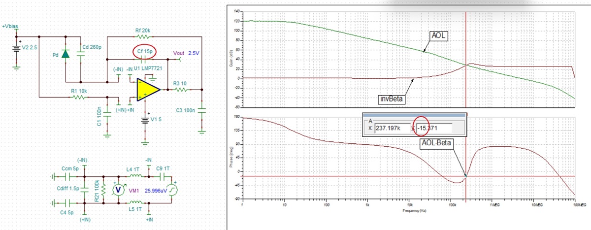
    Any attempt to increase the bandwidth to 530 kHz by lowering the Cf down to 15pF would result in unstable system showing -15 degrees phase margin.

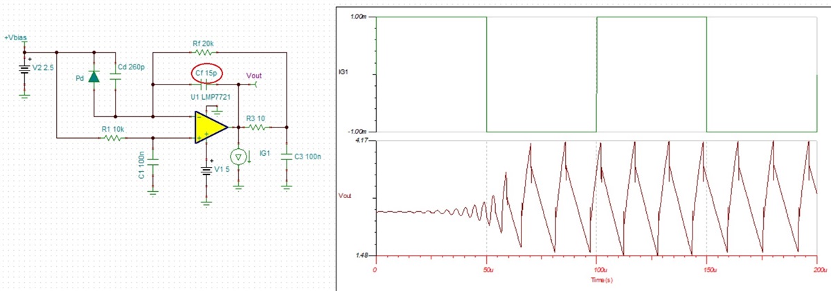
    This may be confirmed by transient simulation showing a sustained oscillation - see below.

    In order to assure stability of the system and minimize the phase dip the minimum required Cf is 100pF - see below.

    Transient simulation analysis confirm stability of the system with miniscule overshoot- see below.

    4606.LMP7721 AC Stability.TSC

    7411.LMP7721 Transient Stability.TSC