This thread has been locked.

If you have a related question, please click the "Ask a related question" button in the top right corner. The newly created question will be automatically linked to this question.

LMH5401: LMH5401 Single-ended Input into Non-inverting Input

Part Number: LMH5401

The datasheet for the LMH5401 as well as most of the reference design circuits I see use it in an inverting configuration (single-ended into inverting input terminal). Is this the optimal configuration for this component? I have simulated a circuit where I input a single-ended signal into the non-inverting input terminal, and the results seem to be fine. 
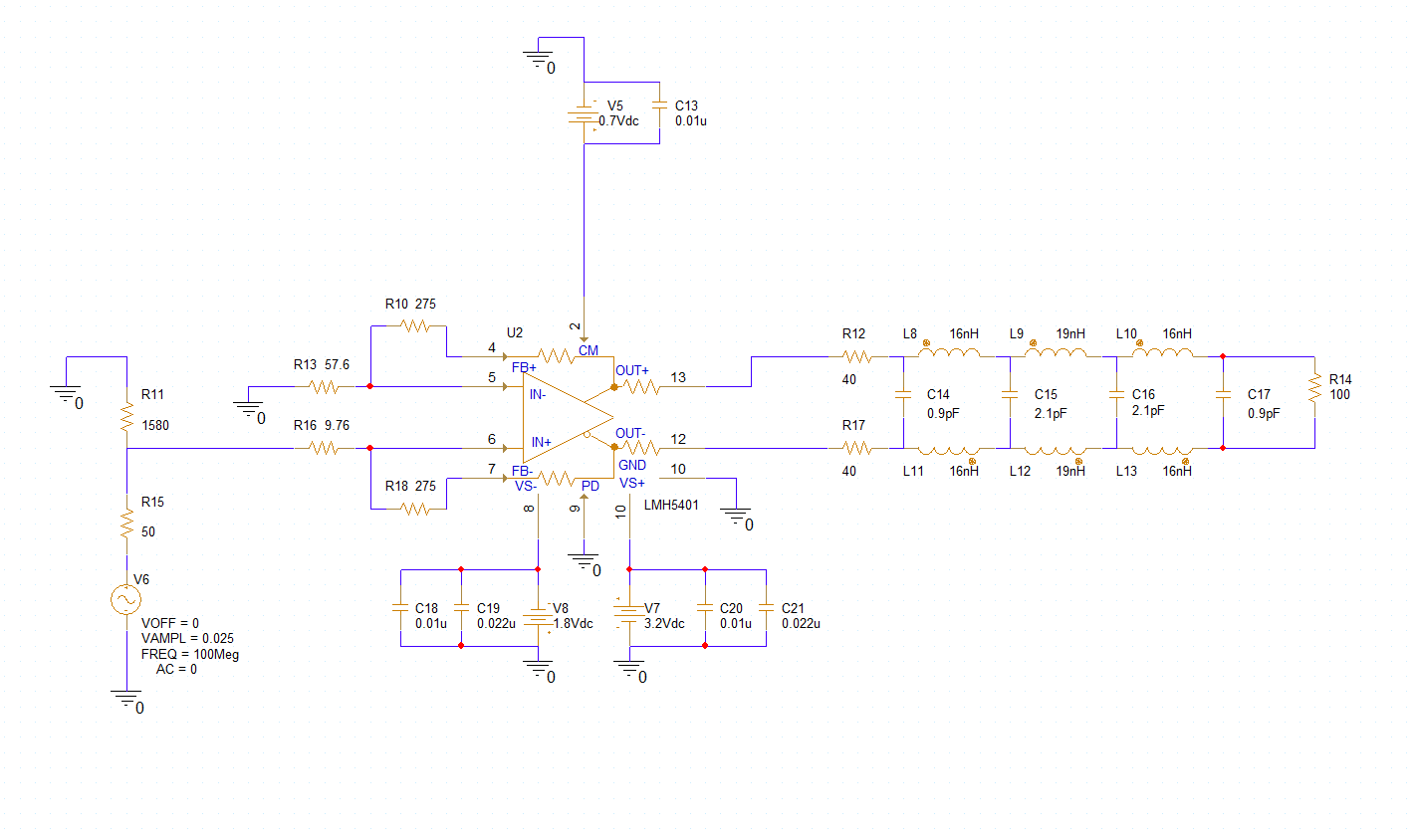
image.png

  • Replying here to see if anyone has any input on this question?

  • Hi Shoaf,

    Looking at your schematic, I can see the LMH5401 is configured with RF = 275Ω (R10, R18), RG = 57.6Ω (R13), supplies of +3.2V/–1.8V, and VOCM = 0.7V (midsupply), feeding into an LC bandpass filter and a 100Ω load.

    The LMH5401 is fully symmetrical — the datasheet states: "Either input (IN+ or IN–) can be used for single-ended inputs. The unused input must be terminated." So your simulation results with the non-inverting input are expected and valid.

    The reason most reference designs use the inverting input is about input common-mode behavior. In the inverting configuration, the input common-mode stays essentially constant regardless of signal swing. In the non-inverting configuration, the input common-mode moves with the signal, which at large amplitudes could push outside the specified input range and cause clipping. At your signal level (25 mV), this is negligible — which is why your sim looks fine. If you ever increase signal amplitude significantly, verify the input common-mode stays within VS– to about VS+ – 1.5V (–1.8V to +1.7V with your supplies). The inverting configuration avoids this concern entirely and gives a more predictable input impedance, which is why it's the standard recommendation — but there's no performance penalty either way.