This thread has been locked.

If you have a related question, please click the "Ask a related question" button in the top right corner. The newly created question will be automatically linked to this question.

TAS6501-Q1: 0x86 register PVDD flag set at start up

Part Number: TAS6501-Q1

I have a question regarding register 0x86 in TAS6501-Q1.

During initial power ON of the amplifier will both bits be set:

  • DVDD POR STORED
  • PVDD UV STORED

Do we need to read this register at startup to clear both bits, before initializing the amplifier?

Is there internal circuitry in the amplifier cutting PVDD when PD is LOW? How it is then turned back ON?

What we observe in our application is that PVDD UV STORED is set to 1 when we enable the amplifier via ~PD=HIGH.

On PVDD we have battery voltage which is constant during operation time of the cluster. DVDD is OFF during PD mode and enabled around 500ms before the amplifier is turned ON.

Thanks for the support.

  • Hi Vladimir,

    Anytime TAS6501-Q1 goes through a power up (/PD transitions from LOW to HIGH) the DVDD POR flag will be set to 1 and will only be cleared when the clear fault bit 3 in the Reset register 0x1 is set to 1.

    PVDD or DVDD UV flags will only be set if after power up  (/PD is HIGH) the voltage for DVDD or PVDD was below their respective UV thresholds.

    Do we need to read this register at startup to clear both bits, before initializing the amplifier?

    Yes, that would be a good practice after every system controlled power up, before reading faults.

    Is there internal circuitry in the amplifier cutting PVDD when PD is LOW?

    There's no internal circuits disconnecting PVDD when /PD is low. It only disables the internal circuits that run off PVDD supply.

    How it is then turned back ON?

    PVDD isn't tuned off on unless your system removes PVDD power. When /PD goes HIGH, if PVDD voltage is above UV threshold the internal circuits running off PVDD is enabled. if PVDD voltage is below UV threshold the internal circuits running off PVDD remains disabled and PVDD UV is reported.

  • Hi Damian 

    Currently we observe that the flag PVDD UV STORED  is set along DVDD POR after enabling the amplifier despite VPDD is stable, in our application PVDD is connected to VBATT.

    What is the explanation behind?

  • Hi Vladimir,

    Do you have a schematic I can reference? I would also recommend capturing your PVDD, DVDD and /PD voltage during power up to confirm that's the case.

  • Hi Damian

    Regarding the schematic I will not be able to share it because it is a product in development.

    Green - VBATT

    Yellow - AMP_EN

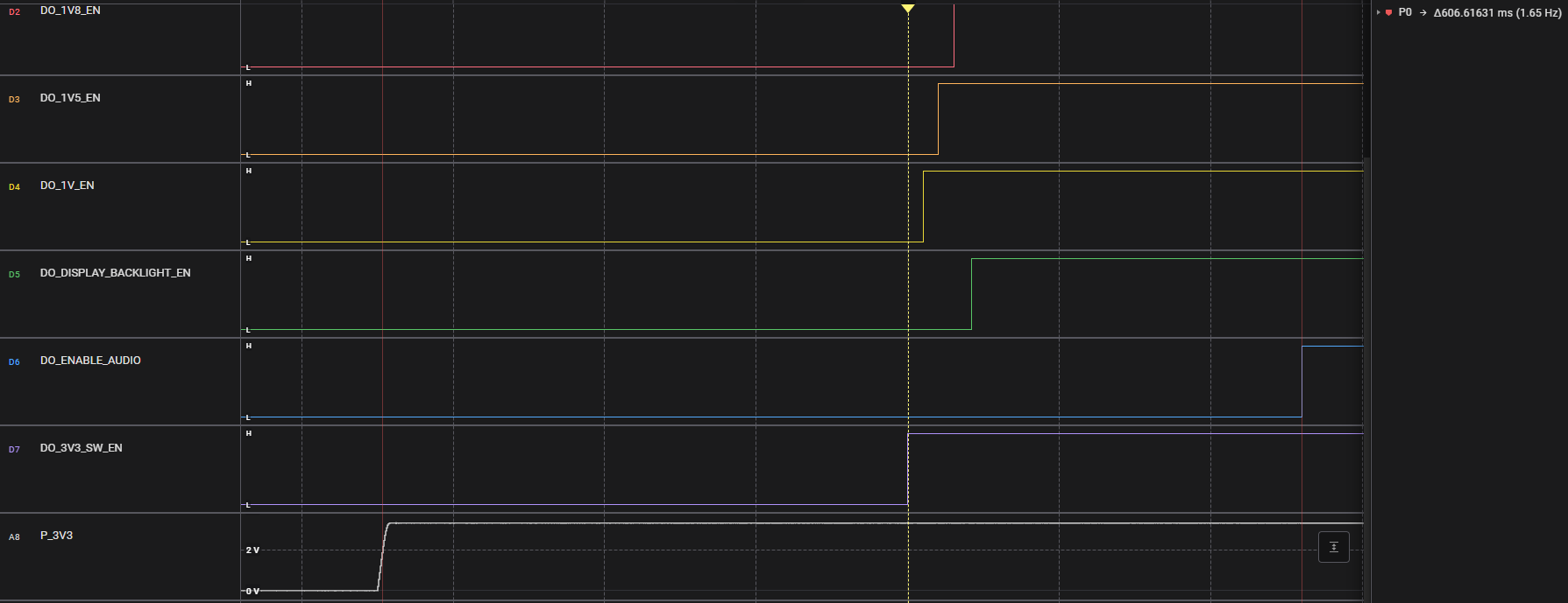
    P_3V3 starts with CAN INH, the AMP is enabled about 600ms after.

    The point is that we get PVDD UV FLAG set.

  • Hi Vladimir,

    My apologies. Your observation is correct and normal for this amplifier. I got it a little confused with our higher power amplifiers that has separate /PD and /STBY pins where /PDN is for the digital circuits and /STBY is for the analog circuits. /PD pin for TAS6501 controls the power up and down for both digital and analog circuits, you will observe DVDD POR and PVDD UV flags being set to 1 when /PDN goes from LOW to HIGH. These two falgs (DVDD POR and PVDD UV) are cleared on read, so clear fault command (clear fault bit 3 in the Reset register 0x1 is set to 1) is not needed. A secong read of the flags should confirm they were cleared by the first read. 

  • Hi Damian

    Thank you for your support. Than I would expect datasheet correction on TI side to include this statement.

    This solved our issue.