This thread has been locked.

If you have a related question, please click the "Ask a related question" button in the top right corner. The newly created question will be automatically linked to this question.

LM2917-N: design check

Part Number: LM2917-N

Hi

The many permutations and design options for the LM2917 leave me unsure we have the design right.  I wanted feedback if the circuit is correct.

Requirement:
fan tachometer output - need to trigger indicator (1/0) whether fan tach output is above or below 300Hz

two of these to be input to a logic circuit to drive bi-lvel LED - green if both OK, RED if EITHER is below 300Hz

1) We assumed "speed switch" for figure 18 in the datasheet was the simplest approach with minimal parts - is this correct?

2) We adjusted some part values for the frequency and voltage relevant.

3) we fed the output at collector with pullup to a NOR

is the choice of 2917/2907/8 pin/14 pin correct?
is the schematic correct?fan tacho.jpg
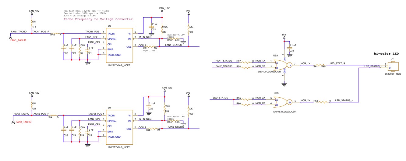
are the values correct?

thanks

Pinhas

  • Hi Pinhas, 

    What is the signal FAN2_TACHO waveform amplitude and shape? Also what is an acceptable error tolerance for your output? 

    Regards,
    Ashley

  • Both FAN1_TACHO and FAN2_TACHO are square wave with 12V amplitude (0-12V), acceptable error tolerance +/-10%
    From fan datasheet-
  • Hi Pinhas, 

    Thank you for the additional information. Please give me until end of day tomorrow (Wednesday 02/25) to review the schematic and provide my feedback. 

    Regards,
    Ashley

  • Hi Pinhas, 

    For your input signal amplitude, this will need to be within the input common mode range of the amplifier: 

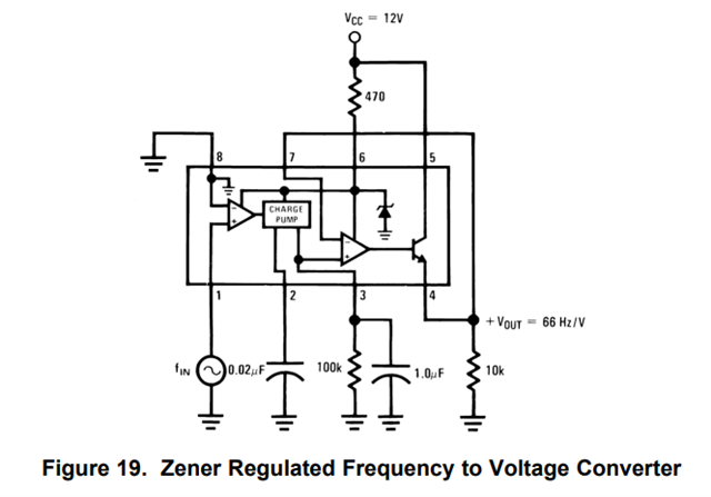
    Based on your application, it appears that you are wanting to take the tachometer output (square wave) and convert the frequency to a voltage. I recommend using Figure 19 in the datasheet to simplify the conversion. Or if you want the output to latch at a certain frequency, there is an overspeed latch circuit (Figure 11). 

    This application note goes more in-depth into the different circuit options: AN-162 LM2907 Tachometer/Speed Switch Building Block Applications

    Best regards,
    Ashley

  • Hi Ashley,

    thanks.
    indeed - we do not need to know the frequency, just need to change a bilevel LED from green to red when the level goes below a certain frequency.

    thus we used the figure 15 speed switch from the datasheet.

    how does the figure 9 speed switch (from the app note?) differ - if at all?  I think it may be the same circuit.

    If so we are set on the layout - but would appreciate feedback if we got the values right for the voltage and threshold frequency mentioned of 300Hz

    and thanks for the app note link - we will look at it


    thanks
    p

  • Hi Pinhas, 

    I compared the two circuits (basic frequency to voltage converter and speed switch) and it appears that the basic functionality are the same, the main difference is the speed switch circuit uses the comparator on the output to either set the output high or low based on the threshold set. 

    Your circuit implementation was slightly modified from the circuit recommendation so I was not familiar with this method, but the values selected should work for the threshold of 300Hz.

    Please let me know if you have further questions.
    Thank you!

    Best regards,
    Ashley