This thread has been locked.

If you have a related question, please click the "Ask a related question" button in the top right corner. The newly created question will be automatically linked to this question.

INA849: Regarding the unused Pins

Part Number: INA849

Dear Team, 

I am Planning to use this INA849DGKR part in my design,

Please find the attached Snap shot
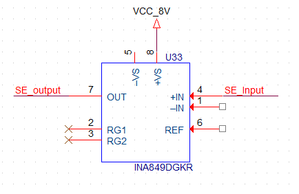
image.png

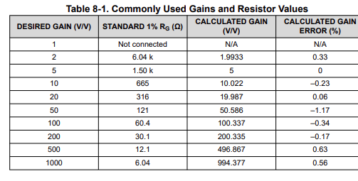
I want G=1,  so as per te given table i left it as Not connected, image.png
Please adivise me how to terminate VS- and IN- pins, also advise me how to use REF pin and why REF is needed. Can i terminate it to GND of 2.5V should be given as mentioned in datasheet?.

Looking forward to your reply, 

Thank you and best regards, 
Maharajan P

  • Hi Maharajan,

    We have a lot of great reference material to help you learn all about instrumentation and difference amplifiers. Precision labs series: Instrumentation amplifiers | TI.com is a great introduction to both types of amplifiers as well as more advanced topics. 

    Please adivise me how to terminate VS- and IN- pins, also advise me how to use REF pin and why REF is needed. Can i terminate it to GND of 2.5V should be given as mentioned in datasheet?.

    In order to answer some of these questions, I'll need to better understand what it is you are trying to do. My questions for you:

    • What does your input signal look like? 
      • What is the voltage range? 
    • What do you want the output voltage range to be? 

    The REF pin is needed to help adjust your common mode voltage on the output. This can greatly affect the voltage range of your output. Take a look at the Analog Engineer Calculator Tool to test different voltages for the boundary plot (Vcm vs Vout).

    Best Regards,

    Robert Clifton