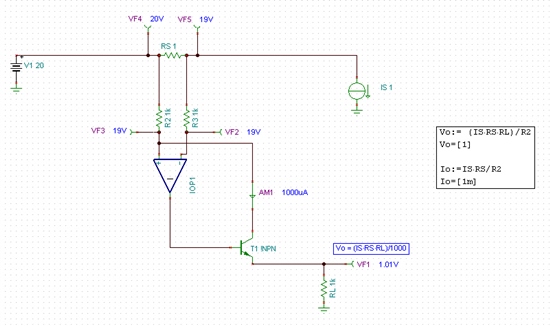
Can somehow show me a DC circuit analysis for this INA13X part, starting with series resistor Rs, then using differential amplifier, via BJT transistor, to the output voltage formula.
Thanks
Can somehow show me a DC circuit analysis for this INA13X part, starting with series resistor Rs, then using differential amplifier, via BJT transistor, to the output voltage formula.
Thanks