


Part Number: AMC23C10
Hello Team,
I am planning to use the AMC23C10 isolated comparator for a zero-cross detection (ZCD) circuit with an AC mains input.
In the datasheet application circuit, it appears that the input return (GND1) on the primary side is connected in a way that could be interpreted as being tied to the AC neutral. Since I am using a low-voltage supply (around 5V) on the primary side, this raises a concern:
If the primary-side ground (GND1) is connected to AC neutral, does that effectively short the low-voltage ground to the mains neutral? Is this configuration safe and recommended?
I would like clarification on the correct way to connect:
-
AC mains (Line/Neutral)
-
Primary-side supply (VDD1, GND1)
-
Isolation boundaries between primary and secondary sides
Specifically:
-
Should GND1 be directly connected to AC neutral, or should it remain floating?
-
What is the recommended safe grounding scheme when using AMC23C10 for ZCD in mains applications?
Any guidance or reference design would be very helpful.
Thanks in advance.
Subject: Clarification on Grounding and Neutral Connection for AMC23C10 in ZCD Application
Hello Team,
I am planning to use the AMC23C10 isolated comparator for a zero-cross detection (ZCD) circuit with an AC mains input.
In the datasheet application circuit, it appears that the input return (GND1) on the primary side is connected in a way that could be interpreted as being tied to the AC neutral. Since I am using a low-voltage supply (around 5V) on the primary side, this raises a concern:
If the primary-side ground (GND1) is connected to AC neutral, does that effectively short the low-voltage ground to the mains neutral? Is this configuration safe and recommended?
I would like clarification on the correct way to connect:
-
AC mains (Line/Neutral)
-
Primary-side supply (VDD1, GND1)
-
Isolation boundaries between primary and secondary sides
Specifically:
-
Should GND1 be directly connected to AC neutral, or should it remain floating?
-
What is the recommended safe grounding scheme when using AMC23C10 for ZCD in mains applications?
Any guidance or reference design would be very helpful.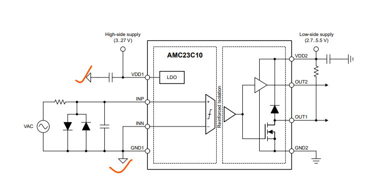
Thanks in advance.

