OPA549: AMPLIFIER

Part Number: OPA549

Hi,

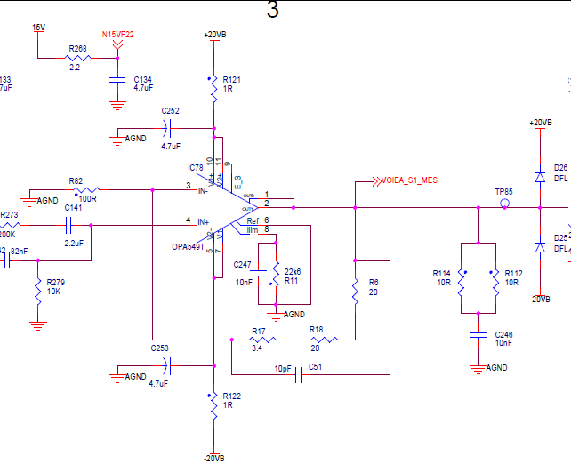
I'm using the circuit schematic for four channels that is attached.

For whatever reason, the gain on one channel is 1.4356 instead of 1.434. 

The resistors used for feedback are the same.How can we account for this variation in gain?

Thank you for your help.


image.png

  • Hi Yvan,

    Let's start with the schematic. It looks like you are configuring the OPA in a non-inverting amplifier with some component of an AC coupled path. I see that R279 also pulls IN+ to GND with another ac coupled input (schematic is clipped, so I cannot see all components). 

    The OPA is configured in a non-inverting gain of 1 + ((20 + 20 + 3.4) / 100) = 1.434V/V ideal. 

    Remember, the OPA uses its very high open loop gain to realize accuracy in the transfer function, so any gain error here would likely not be caused by the OPA. 

    The most likely issue here is resistor tolerance causing gain error to appear. If we calculate the gain error here, we see that you have about .1% error. This is very much expected error for something like .1% to 1% resistors. 

    If you need better accuracy than this, you may need to use precision resistors, or use something like a matched resistor pair to realize the required low gain error. 

    What requirements do you have in this application? 

    Thanks,

    Jacob

  • Hi Jacob,

    R6=R18 =20R à 0.1%

    R17=3.4 à 1% et R82=100R à 0.1%

    The results show that the minimum gain is 1.4328 and the greatest gain is 1.4351. Theoretically, in order to satisfy the requirement, I should have the same gain. This error can be corrected by adjusting the settings beforehand


    However, this is still unexpected because the other 3 channels—I should mention that they employ the same batch of components—are operating as intended.

    Would there be a problem with a single amplifier, given that an open-loop operational amplifier offers a gain of 110 dB – couldn’t it have a much lower gain?
    I need to set the gain to 1.3 on this channel in order for it to function?

    Thanks for your help

  • Hello,

    I see. 

    Gain closed loop = AOL/( 1+AOL*Beta) = 10^5.5 / (1+ (10^5.5* (1/1.434))) = 317,228 / (1 + (317228 *.69735) = 1.43399349 V/V = .00045397% GE

    All goes to say that we do not really need to be scared of lack of loop gain, especially given that 1/Beta is so low. 

    100dB of loop gain translates to .001% GE, so it makes sense that we are slightly better than this. 

    Now as for what you mention, resistors are a bit strange, and some manufacturers employ strategies which cause headaches. 

    One of the lesser known strategies involves "binning" where a thick film resistor is literally tested and separated out into .01%, .05%, .1% ..etc. Not all manufacturers do this, but the result is in that we have a truncated gaussian distribution when we test resistors for %TOL. 

    One of the other effects is just as you mention, lot dependencies. We even see in our semiconductors at TI, batches and lots tend to certain levels of mean shifting based on various process related effects. It is very likely that the same thing may be happening here. 

    I suspect that the "error" follows the resistors, and you could check if you happen to have a precision DMM on hand. Just measure the resistor chain and compare between devices to see if this particular circuit has larger error. This would allow us to calculate the real gain setting of the feedback network, confirming if the error is in resistor mismatch. 

    Alternatively, you can ABA swap one of the IC's from the good circuit into the place of the error circuit. This should show that the error is still present. 

    Thanks,

    Jacob

  • Hello Jacob,

    I appreciate your tremendous assistance.
    As soon as I have the amplifier, I'll absolutely replace it, and I'll update you.

    Thanks,

    YD

  • Happy to help. I am looking forward to the data. 

    Best,

    Jacob