This thread has been locked.

If you have a related question, please click the "Ask a related question" button in the top right corner. The newly created question will be automatically linked to this question.

XTR200: XTR200, 0-10V output.

Part Number: XTR200
Other Parts Discussed in Thread: TLV9001, AMC1351, OPA310, OPA320

Hi guys. 

I'm trying to build an isolated 0-10V circuit using an XTR200 and an AMC1351QDWVRQ1. Schematic is as follows:
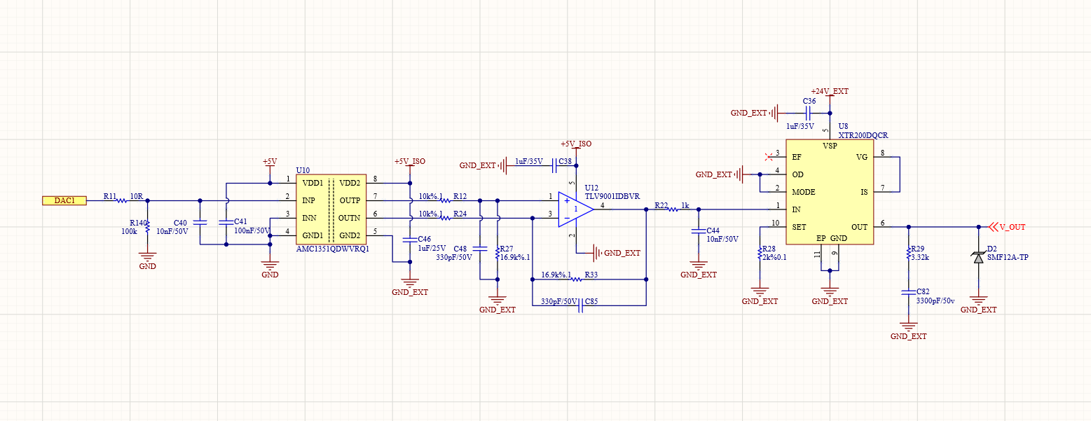

0-10V.png


Circuit is working good but with the DAC output at 0V, I'm seeing a value close to 50mV at the 0-10V output. So I can't pull the XTR output to exactly 0V. Is there a way to do this? Can I pull the output to 0V using the OD pin or another method?

Thanks.

  • Hi Ahmet, 

    Could you clarify what voltage you are measuring on the input of the XTR200? (Pin 1) 
    At each stage of the signal path, what is the voltage when the DAC is 0V?

    Thank you!

    Regards,
    Ashley

  • Hi Ashley.

    I am using ST MCU. The DAC voltage never drops to 0. Minimum 1mV. I'm measuring 0.4mV at the AMC1351 differential outputs when the DAC output is 1mV. This means the AMC1351 is working correctly. However, I'm measuring approximately 15mV at the output of the TLV9001. Therefore, I'm also measuring 15mV * 3.75 = 56mV at the output of the XTR200. I think the problem stems from the op-amp output not dropping completely to 0V. What can I do in this situation? Can I eliminate this 50mV offset by using the OD pin of the XTR200?

    Best regards.

  • Hi Ahmet, 

    Could you clarify why you need the differential output isolation amplifier for in your design instead of a single-ended? It seems like you need the TLV9001 in a difference amplifier configuration to convert the differential signal to single-ended and this is adding the additional offset voltage. I'm not sure why the offset is that high, but would like to understand the signal chain path first. 

    How close to 0V on the XTR output are you aiming to achieve? And what is connected to the output of the XTR?  

    Best regards,
    Ashley

  • Hi Ashley.

    When I first started the project, I couldn't find an isolated single ended amplifier. The reason for the offset voltage occurring in the TLV9001 is, I believe, because the op-amp's output doesn't drop completely to 0V due to the lack of a negative power supply. This project is an industrial-grade 0-10V output circuit. Therefore, I'm trying to ensure the output pin drops completely to 0V. The output pin of the XTR is connected to the socket.

    I'm thinking of eliminating the offset voltage by adding a negative -5V supply to the circuit and changing the op-amp. This requires adding extra components.

    However, can I pull the XTR output to 0V by controlling its OD pin? Will setting the OD pin high cause the output to drop to 0V?

    Thanks.

  • Hi Ahmet, 

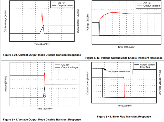
    You can set the device to output disable mode to force to 0V, but there is a transient response associated with turning the OD pin on and off (shown in Figures 5-40 and 5-41) which can impact your output linear response if you are trying to measure from 0-10V accurately. 

    Please also note that 0V on the output of the XTR will be slightly above 0V by at most a few mV.

    It looks like the TLV9001 is set in a gain of 1.69, could you clarify what the range of the DAC will be and if this is why there is a gain stage before the XTR?

    Best regards,
    Ashley 

  • Hi Ashley.

    DAC output voltage is max 4.0V. AMC1351 gain is x0.4. XTR output formula is here;

    XTR_Output = DAC_Voltage * AMC_Gain * TLV_Gain * XTR_Voltage_Constant
    XTR_Output = 4.0 * 0.4 * 1.69 * 3.75
    XTR_Output = 10.14V max.

    DAC voltage is not enough for 10V output. Because AMC1351 gain is 0.4.

    If disable XTR output using the OD pin, the output voltage doesn't drop exactly to 0. I understand that. A few millivolts is acceptable. But 50mv is so much. 

    So, by using the OD pin, I can pull the output voltage down to a value close to 0V. Is that correct?

    Thanks.

  • Hi Ahmet, 

    Is it possible to sweep the DAC input from 0-4V and probe what the TLV9001 output and XTR200 output is? I would like to see what the sweep looks like if the possible cause of the issue is an offset voltage problem or output swing limitation. 

    Can you confirm what the accuracy of the resistors surrounding the TLV9001 are (R12, R24, R27, R33)? 0.1%? 

    Even if you set the OD pin and pull the output voltage to 0V, the output pin will be in high impedance and if there is a load that needs to be driven on the output side, this cannot be driven properly. Can you clarify what is directly connected after the socket? What is the 0-10V output then connected to? 

    Also, can you clarify what the isolation barrier is for? 

    Thank you!

    Best regards,
    Ashley

  • Hi Ashley.

    When I increase the DAC voltage from 0 to 4V, the output of TLV and the output of XTR increase quite consistently according to the formula. However, until the DAC voltage reaches 20mV, I see 13mV at the TLV output and 50mV at the XTR output. So there's a constant offset at the TLV output.

    All resistors have a 0.1% tolerance.

    Any device operating on 0-10V (motor driver, fan speed controller, heater, etc.) can be connected to the socket. It doesn't matter if the output is 0V and the load at the output isn't driven when I set the OD pin to 0. I want to turn off the output when I set the OD pin to 0.

    This system has many communication, read/write, and analog IO's. I need to protect the system from noise. 

    Thanks.

  • Hi Ahmet, 

    What is the resolution of your DAC? And what is the target resolution needed on the output of the XTR? 

    I am a bit confused when you are saying that the DAC voltage from 0 to 4V results in the output of the TLV and XTR to increase consistently per the formula but is the output constant between DAC input 0-20mV? 

    Regards,
    Ashley

  • Hi Ashley.

    DAC resolution is 12bit. I believe the XTR output will also be 12-bit resolution. That is, 10V / 4096 = 0.0024V per bit. 

    I've prepared a measurement tabel to help you understand better.

    DAC output = 1mV --> AMC output = 0.4mV --> TLV output = 13mV --> XTR_Output = 48.75mV

    DAC output = 2mV --> AMC output = 0.8mV --> TLV output = 13mV --> XTR_Output = 48.75mV 

    DAC output = 3mV --> AMC output = 1.2mV --> TLV output = 13mV --> XTR_Output =  48.75mV

    DAC output = 4mV --> AMC output = 1.6mV --> TLV output = 13mV --> XTR_Output =  48.75mV

    DAC output = 5mV --> AMC output = 2mV --> TLV output = 13mV --> XTR_Output =  48.75mV

    DAC output = 6mV --> AMC output = 2.4mV --> TLV output = 13mV --> XTR_Output =  48.75mV

    DAC output = 7mV --> AMC output = 2.8mV --> TLV output = 13mV --> XTR_Output =  48.75mV

    DAC output = 8mV --> AMC output = 3.2mV --> TLV output = 13mV --> XTR_Output =  48.75mV

    DAC output = 9mV --> AMC output = 3.6mV --> TLV output = 13mV --> XTR_Output =  48.75mV

    DAC output = 10mV --> AMC output = 4mV --> TLV output = 13mV --> XTR_Output =  48.75mV

    DAC output = 11mV --> AMC output = 4.4V --> TLV output = 13mV --> XTR_Output =  48.75mV

    DAC output = 12mV --> AMC output = 4.8V --> TLV output = 13mV --> XTR_Output =  48.75mV

    DAC output = 13mV --> AMC output = 5.2mV --> TLV output = 13mV --> XTR_Output =  48.75mV

    DAC output = 14mV --> AMC output = 5.6mV --> TLV output = 13mV --> XTR_Output =  48.75mV

    DAC output = 15mV --> AMC output = 6mV --> TLV output = 13mV --> XTR_Output =  48.75mV

    DAC output = 16mV --> AMC output = 6.4mV --> TLV output = 13mV --> XTR_Output =  48.75mV

    DAC output = 17mV --> AMC output = 6.8mV --> TLV output = 13mV --> XTR_Output =  48.75mV

    DAC output = 18mV --> AMC output = 7.2mV --> TLV output = 13mV --> XTR_Output =  48.75mV

    DAC output = 19mV --> AMC output = 7.6mV --> TLV output = 13mV --> XTR_Output =  48.75mV

    DAC output = 20mV --> AMC output = 8mV --> TLV output = 13mV --> XTR_Output =  48.75mV

    DAC output = 21mV --> AMC output = 8.4mV --> TLV output = 14.2mV --> XTR_Output = 53,25mV

    DAC output = 22mV --> AMC output = 8.8mV --> TLV output = 14.8mV --> XTR_Output = 55,5mV

    DAC output = 23mV --> AMC output = 9.2mV --> TLV output = 15.5mV --> XTR_Output = 58.12mV

    DAC output = 24mV --> AMC output = 9.6mV --> TLV output = 16.2mV --> XTR_Output = 60.75mV

    DAC output = 25mV --> AMC output = 10mV --> TLV output = 16.9mV --> XTR_Output = 63,37mV

    As you can see, the TLV output remains constant until the DAC voltage exceeds 20mV. After 20mV, it increases very linearly.

    I hope I've explained it clearly.

    Thanks.

  • Hi Ahmet, 

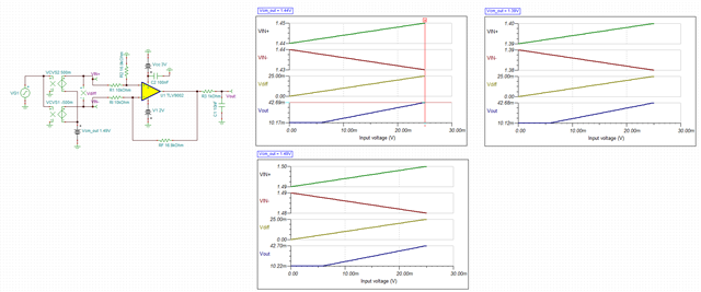
    I believe this issue is caused from hitting the VOL limit on the TLV9001. I would recommend trying to use the OPA310 as a replacement to see if you can get closer to the negative rail on the output and reduce the error margin. 

    I've attached the TINA simulation to show the op amp behavior with the input conditions as close to the AMC device as possible (differential signal with output common mode). 

    tlv9002_xtr200_e2e.TSC

    Please let me know if you have any questions.

    Thank you!
    Best regards,
    Ashley

  • Hi Ashley.

    So I'll try 3 methods.
    1- I'll use OPA320 instead of TLV9001 (I don't have OPA310)
    2- I'll set the OD pin of the XTR200 to 0V.
    3- I'll negative-power the op-amp.

    The problem is likely due to the op-amp not supplied with negative voltage. With a single supply, the output cannot approach 0V.


    Thanks for your support.