This thread has been locked.

If you have a related question, please click the "Ask a related question" button in the top right corner. The newly created question will be automatically linked to this question.

ALM2403-Q1: Input sinuoid generation, phase shift and synchronization in Resolver front end

Part Number: ALM2403-Q1
Other Parts Discussed in Thread: TINA-TI

Im using ALM2403-Q1 for the resolver excitation. 

Im refering SBOA504 for the implementation. Image attached below.image.png
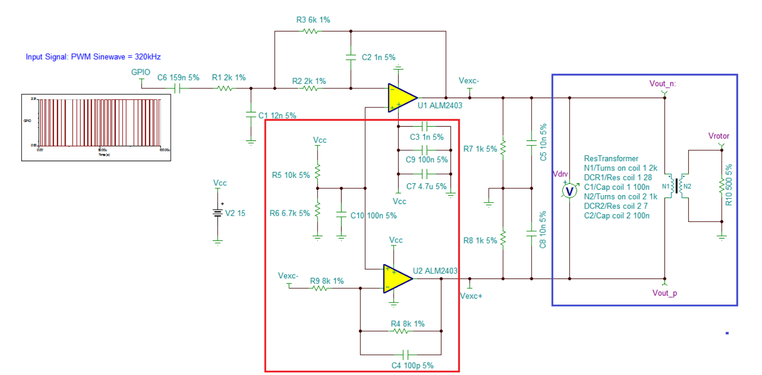
Question 1: why do we generate spwm for resolver input? why not just generate using DAC and feed to the ALM2403 eliminating the need of 2nd order filter?

Question 2: I dit the ltspice simulation of the exact model given in the picture above, it introduced large phase shift of 56 degrees in the output, so how to synchronize the resolver feedback ADC sampling with this shifted outupt given by ALM2403? 

  • Hi Narendra,

    1. SPWM is often selected as not all designers have access to a dedicated DAC in resolver drive applications. DAC's or AWG are the preferred method to generate the analog signal, though they often require another IC outside of the MCU, or require relatively higher data handling on the MCU side. DAC would help you eliminate some of the filter network.

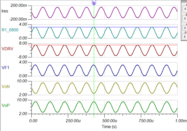
    2. Some phase shift is expected as the multi-order filter + reactive resolver load will naturally cause phase delay. You can drastically improve this parameter with a design like this:

    Sine 10kHz ALM2403 .TSC

    Please let me know what you think of this new simulation. Do you have any parameters you want to accomplish for the resolver driver?

    Thanks,

    Jacob

  • Hi Jacob,

    Thanks for clarification! The file you provided is not opening in TINA , but ill replicate that in LtSpice and check out.

  • Hey Narendra,

    Whoopsies, my TINA version was set incorrectly. 

    Here is the TINA-TI version in case you wanted to play around with the simulation. 

    Sine 10kHz ALM2403_V7.TSC

    Thanks,

    Jacob