This thread has been locked.

If you have a related question, please click the "Ask a related question" button in the top right corner. The newly created question will be automatically linked to this question.

IVC102 reset-and-integrate measurement:

Other Parts Discussed in Thread: IVC102

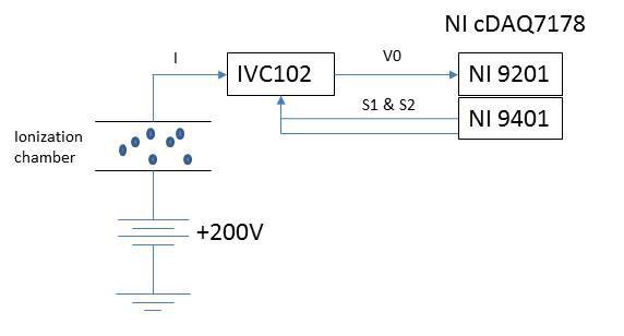
I have acquired a BB IVC102 precision amplifier for detecting small currents originating from an ionization chamber.

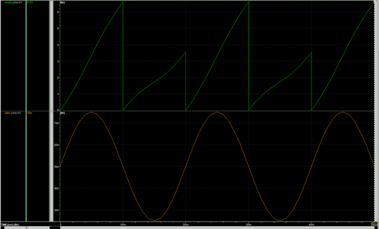
In order to detect currents up to 100nA, I am integrating for 10ms before closing S2 for 10us and starting a new measurement. When I monitor V0 during 10 consecutive integration periods, the EVEN and UNEVEN voltage ramps are markedly different. For example, ramps 1-3-5-7-9 each reach 1V after 10ms, while ramps 2-4-6-8-10 each reach 0.65V.

The current provided by the ionization chamber is fairly constant and is certainly not expected to fluctuate with such a methodic behaviour, so I suspect this is a phenomenon introduced by the IVC102.

Any help explaining this behaviour would be greatly appreciated.

Thanks, Pieter

  • Pieter,

    That is indeed an odd behavior and it is difficult to imagine how the IVC102 could be the cause. My first guess is that there is a difference in the timing. I encourage you to carefully inspect the timing waveforms to assure that they are identical on alternate cycles. This includes the integrate, hold and resest timing periods. If you have further problems, please provide a schematic and we will attempt to help.

    Regards, Bruce.

  • Hello Bruce,

    Well, actually I inspected the S1 and S2 timing signals accurately before starting my measurements. S2 is generated with a National Instruments DAQ system, i.e. NI cDAQ1778 with digital module NI9401. A counter is set-up to create a pulse train 10us low and 9990us high. I have inspected the signal with a scope, but I cannot identify a difference between alternate pulses generated by the counter.

    Above you can find a schematic of my set-up. I have used a prototyping electronics board to deploy the IVC102.

    Regards, Pieter

  • Pieter,

    Your block diagram helps but a detailed schematic might be more revealing.

    I assume that you have connected the internal capacitors for a total of 100pF integrating capacitance. Correct? So an integrated output of 1V for 10ms relates to a 100nA input current. You show the NI 9401 controlling both S1 and S2. I assume that the S1 control signal is a continuous logic high, correct?

    It appears that you are measuring the output voltage with the NI 9201. Are you confident of the timing of this measurement? Perhaps time delays in the measurement are causing the sampling to occur at different times. Have you looked at the integrator waveform with an oscilloscope? Do alternate integration ramps end at different voltages as observed on the oscilloscope? If the integrator waveforms appear the same on alternate cycles then there must be a timing problem in the sampling of the voltage. An integration followed by a hold period prior to reset allows for more variability or "grace period" in the measurement timing.

    I assume that you have connected the internal capacitors for a total of 100pF integrating capacitance. Correct? So an integrated output of 1V for 10ms relates to a 100nA input current. You show the NI 9401 controlling both S1 and S2. I assume that the S1 control signal is a continuous logic high, correct?

    Next step in trouble shooting, I suggest that you eliminate the chamber as a possible cause. Create an independent source of test current to the input--a 10M-ohm resistor connected to a 1V voltage source. This should provide a reliable 100nA current to test the circuit. Do you get the same result?

    Regards, Bruce.

  • Bruce,

    We have updated our prototyping board with the IVC102 to a more properly designed board and ionization chamber, but still observed the same phenomenon. However, with help of some of my colleagues, we managed to isolate the problem with help of a current source, as you suggested in your earlier post, and eventually solve it.

    we had a strong pick-up of 50Hz background signal.

    Just getting back to your additional questions:

    • All internal capacitors have been connected for a total of 100pF
    • S1 is a logic high and S2 is as described in Figure 1 of the IVC102 data sheet.
    • The circuit we have implemented initially is an exact copy of Figure 1 in your data sheet, with a 10ms integration time as mentioned above.

    My colleague, Alvaro Geraldes, simulated this circuit with SPICE, adding a 50Hz noise source at the input with an amplitude of 75nA.

    This is exactly what we have been observing all along.

    Subsequently, we started looking for the actual source of this noise:

    • We have verified that is was not originating from our current source.
    • We have upped the value of the bypass capacitors for the power supply to reduce any possible 50Hz noise. This did not change anything, so the 0.1uF appeared to be sufficient
    • In the end, the ion detector plate appeared to be the source of pick-up noise. Properly shielding this with a grounded cage solved our problem.

    Thanks for your help.

    Regards, Pieter

  • Pieter,

    Good work. I'm glad you were able to find the issue.

    Regards, Bruce.

  • Hi Bruce,


    I would like to design a circuit, around the same lines a Pieter, using the LMP 7721 and IVC102 to measure very very low current from a 0.6cc farmer type Ion chamber used in radiotherapy. the sensor input and the guard are at HV upto 1000VDC, the measurement is to have very low noise pick up and it can go up to 10 minutes, so I need to reset after measurement.  The current range of measurement is from as less as 1pA to about 1microA. the measurement are both pulse from Linear Accelarator and well as a steady Cobalt 60 treatment Device.

     Is a Circuit design available??

    Regards

    James

  • Hi Bruce,


    Sorry I forgot to mention, I need to integrate the total current as a charge and display. and then reset it to zero after noting the readings.


    Regards


    James

  • Hi James,

    I am now retired from Texas Instruments and just happened to see your posting. I suggest that you post a totally new question. Questions that are added to the end of a previous thread are often missed by the support staff. They see that the thread already has several responses and expect the previous people involved to respond.

    Best to start a totally new thread.

    Regards, Bruce

  • Hi Bruce,


    I just posted a new question, and I understand Mr. Paul Grohe, is supporting, on very very low current measurement. Hope he see the question."Very Very Low...."


    Best Regards


    James