This thread has been locked.

If you have a related question, please click the "Ask a related question" button in the top right corner. The newly created question will be automatically linked to this question.

OPA656: Higher standby current

Part Number: OPA656

Problem reported: A new batch of boards we have been using for many years are drawing higher-than normal current. The only ICs we are using on those boards are three OPA656 OPAMS. The expected current drawing is 0.004A, but the 80 boards received from are consistently measuring 0.005A.

I noticed that the new failing boards OPAMs have different marking.

image.png

I am wondering if the three OPA656 used in all new 80 boards could be counterfeit components. 

Three bad boards were fixed just by simple replacing the ICs with the ones used in some working boards (with the proper marking).

I did the following test using the bad board (wrong marking) and the working board ICs.

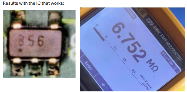
I measure resistance (with the IC outside of the circuit) between pin 5 (VCC) and pin 2 (GND) and these are the results (Ohmmeter + to pin 5, - to pin 2): 

image.png

image.png

image.png


Big difference.

Do I have counterfeits components ??. I purchase some additional ones from Digikey and they have the suspicions markings too. 

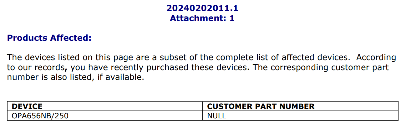
I noticed the following OPA656 die change notice:
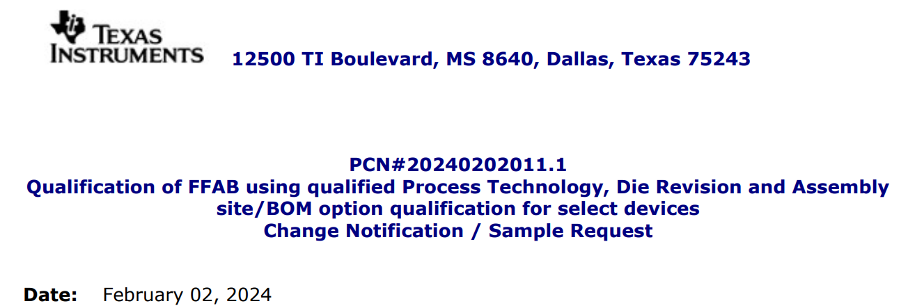
image.png

image.png

image.png


  • Hi ,

    There was change in the die as well to make sure customers do not face supply issues. The markings might have changed. You might have received devices from new fab. Did you purchase the first set of devices through official channels like TI store, Digikey or arrow?

    The quiescent current on OPA656 is 15mA, I am not sure how are you measuring 4mA and 5mA. Could you please share the schematic? 
    Please go through the revision history in datasheet for associated changes. The quiescent current was changed from 14mA to 15mA. Apart from increase in current drawn, are you seeing any failure when you test?

    Thanks
    Vikas J

  • From your email: Did you purchase the first set of devices through official channels like TI store, Digikey or arrow?

    ANSWER: The ICs were purchased from Digikey. I did purchase some extra ones from Digikey once I notice the new marking; they do have the new marking too.
     
    From your email: The quiescent current on OPA656 is 15mA, I am not sure how are you measuring 4mA and 5mA.
    ANSWER:  Our reading is 40 mA in an old (half a year or so) board and 50 mA in the new ones. 40 mA is the total current for the fully populated board.
    As I mention in the schematic: "The board goes back to normal 0.04 Amps as soon as we change the three OPA656 for old OPAMs we have from different old boards"
    The schematic is as follows:
  • My mistake in the original post. The board total standby current is 40 mA in both positive and negative +/- 7V supply.

  • Hi ,

    I see that you are using 3 OPA656 per board. For older device, 40/3 = 13.33mA/device is acceptable supply current.
    For the recently purchased devices, 50/3 = 16.7mA is also acceptable value. Although I am not sure of the accuracy of the measured value. The instrument might have rounded off and is closer to 50mA now. 

    let aside the increase in current, did the circuit fail to work with new devices?
    I am not clear on the statement "good working boards". Is this based on 40mA & 50mA variation alone or was it tested for other parameters like response with some photodiode?

    Thanks
    Vikas J

  • The new boards are working as expected. The 50 mA power supply current load is not just the three OPAMs, but the additional circuitry that is on the board (not shown in schematic). My main concern is that we have been using the same circuit for years and the load is very consistent, and now is changing. As I mentioned before, just by replacing the three OPAMs the current drops to whatever we considered normal. The change in OPAM's VCC pin to Ground pin internal resistance got me worried. 

  • Hi ,

    While we do our best to keep the specs consistent with the older device, there might be some process related changes in the new device. The change in internal resistance might be due to ESD diodes, caps, etc. The increase in the current load is due to the OPA656. I would request you to check the same with higher resolution supply instrument to get the exact change in supply current or individually measure the OPA656 currents to confirm. We have done extensive validation with older devices to make sure the performance remains unchanged on the new device.

    Thanks
    Vikas J