Part Number: AMC3330
Other Parts Discussed in Thread: AMC0230D, AMC1311, , AMC1350, ISO224, AMC0211D
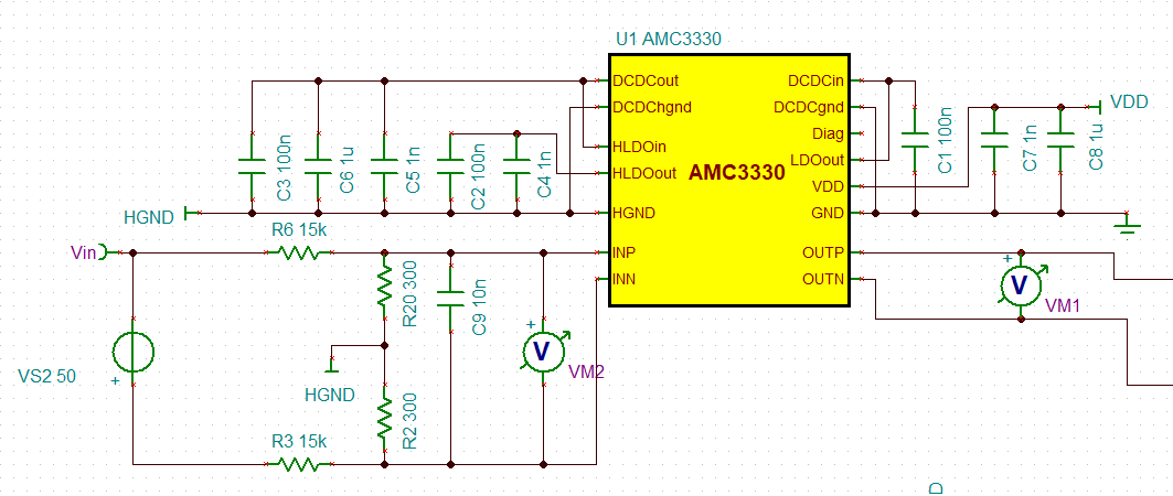
I am designing an isolated ADC circuit and would like to verify my front-end configuration.
My application requires measuring a range of -50V to +50V. Instead of using a standard negative voltage rail, I am planning to implement this by swapping the input wires, as shown in the attached image. Specifically, I will connect +50V to the INN pin and GND to the INP pin (this will be a low-speed, alternating crossover circuit).
I would like to know if the attached schematic is a valid approach for achieving a ±50V input range. Could you please provide guidance or a reference design for this use case?
Additionally, I have a few specific questions:
-
Connection of INN and HGND: Is it mandatory to connect INN to HGND? Could you please explain the technical reason behind this requirement?
-
Floating Inputs: What potential issues or risks (such as Common-Mode Voltage violations) might occur if I leave them unconnected?
-
Device Compatibility: Can I apply this same design topology to the AMC3330, AMC0230D, and AMC1311, assuming I adjust the resistor values accordingly?
Thank you in advance for your help!