This thread has been locked.

If you have a related question, please click the "Ask a related question" button in the top right corner. The newly created question will be automatically linked to this question.

INA199: Requirement for Current Measurement Circuits

Part Number: INA199
Other Parts Discussed in Thread: TIDA-00753, INA228

Hello Team,

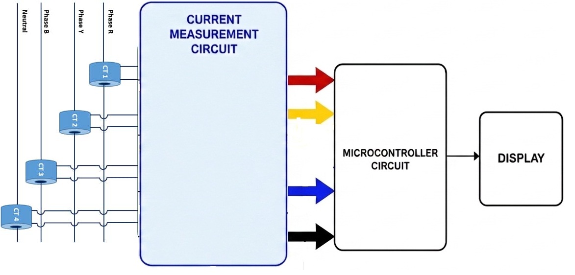
We need to interface a CT with a microcontroller for current measurement. The required measurement range is 0.01 A to 60 A with a 10 mA resolution.

Please find the attached block diagram for better understanding. We require the reference circuit for the blue highlighted section.

Awaiting your response soon.

Thank you in advance.

CT with Microcontroller.jpg

  • Good morning tech iot,

    We actually make a reference design for this type of circuit, located here: https://www.ti.com/tool/TIDA-00753#description. This reference design will give you the reference needed to design such a front end. 

    I have a concern here though in your dynamic range. To size the shunt appropriately for 60A, you limit the amount of sense voltage that your lower boundary (10mA) is going to generate, and therefore offset error dominates. Check out the below analysis on both INA199 and INA296:


    As you can see from the above, in both cases, the lower measurement is effectively destroyed by the offset voltage. You would almost certainly need to calibrate. Is that an option for the solution?

  • Hello Team,

    Thank you for sharing the TIDA-00753 reference design and for the detailed analysis regarding the dynamic range and offset voltage limitations.

    Could you please suggest if there are any other suitable ICs, reference designs, or alternative solutions available in your inventory that are better optimized for wide dynamic range current measurement applications?

    Our target requirement is:

    • Current Measurement Range: 0.01 A to 60 A
    • Resolution / Accuracy: 10 mA
    • Preferably CT-based sensing

    Kindly also advise if there are any newer recommended devices with lower offset characteristics suitable for this application.

    Awaiting your valuable suggestion.

    Thank you.

  • tech iot,

    Thanks for your patience. Carolus is currently out of the office but will reply when he returns Monday, 5/18.

  • tech iot,

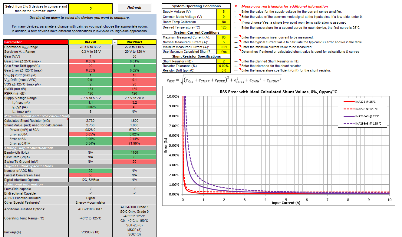
    As I mentioned previously, this is going to be a very hard spec to hit based on a single device. ~4 decades of current measurement is not an easy problem to solve. Check out this application report on the challenges you will face as you design this. From an analog standpoint, with regard to offset and GAIN error, the INA296 I presented up above is the most accurate part that we offer, and as I show below, the error at the lower end is likely unacceptable (72% error). You could also look at this from our digital devices perspective with the INA228, which would greatly simplify the problem, and only possesses 10% error at the 10mA mark:

     However, there is still a problem here in that to achieve the above solution, you now need to find a 2.73mΩ resistor capable of standing up to ~10W of heat dissipation at the maximum condition of 60A before taking resistor derating into account. Other solutions I could recommend would be:

    - potentially investigating multiple devices for each leg to break up the range you are attempting to measure. With this approach you can optimize each device for the portion of the range it is measuring.

    - Implement a switching scheme such as shown in this reference design to break up the range of the device. 

  • Hello Dear,

    Thank you for your response.

    Could you please suggest a suitable CT current measurement circuit using either an Op-Amp or ADC IC (Except INA228) available in your portfolio?

    Additionally, kindly recommend your latest suitable IC along with any reference design or application note for accurate CT current measurement implementation.

    Awaiting your valuable suggestion.

    Thank you.

  • tech iot,

    There is not a readily available reference circuit for this wide of current measurement range that I can give you. The tools above are the closest reference circuits that we have to your application that I can readily share. 

    Regarding op amp or ADC IC's, those would be a separate groups on the forum you would need to ask for recommendations. May I ask why an ADC IC would work here, but the INA228 would not? I would assume that the INA228 is not desired due to the MCU already posessing analog in pins, but I would think that would also invalidate ADC ICs as well?

    To help you further with design, I would need to understand your error budget, power budget, etc., as it makes no sense to make assumptions of shunt resistors, etc. that don't meet the power dissipation needs of the system. From the information above, it appears that 10mA accuracy is desired on the lower bound of 10mA measurement, which is 100% error, is that the case? If so, the simple combination of INA296 swapped out for the INA199 in TIDA-00753 might just work here.