This thread has been locked.

If you have a related question, please click the "Ask a related question" button in the top right corner. The newly created question will be automatically linked to this question.

INA240: INA240 current sensing design

Part Number: INA240
Other Parts Discussed in Thread: REF2033, REF30E

Hello everyone, I am designing a 48V three-phase inverter that will be connected to a BLDC motor controlled using an FOC algorithm at 40kHz.

In fact, the inverter I am designing can be connected either to the "150" motor or the "85" motor, as you can see in the photo below.

Currently, the motor is controlled by another commercial driver, and these are the currents (phase, bus and quadrature) values I have measured:
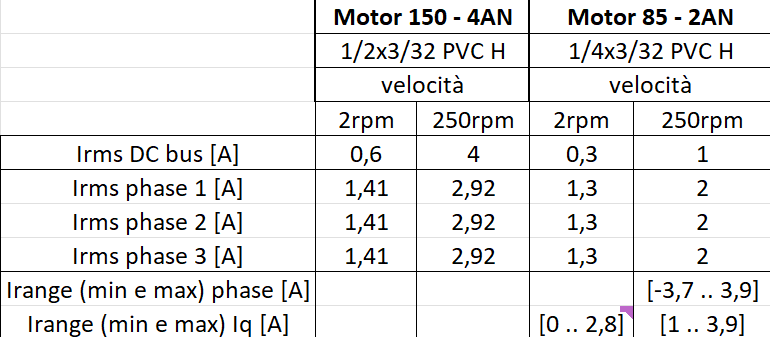
image.png

I will use a microcontroller with a 12-bit ADC.

1) I’ve chosen the INA240 for phase current sensing – do you think that’s the right choice?

2) Is the RMS value sufficient for sizing? Or do we also need the maximum/minimum and peak values?? ..for a rectangular signal Ipk = Irms/D etc.

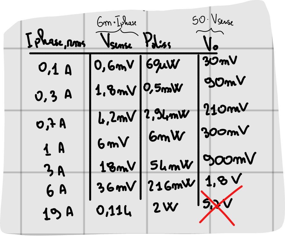
3) Assuming the INA240  is ok and using RMS value, I’ve attached the calculations I’ve done… are they correct?

(for Iphase,max I assumed twice the value of Iphase,max measured using an oscilloscope current clamp, so twice 2,92A .. which is 6A)
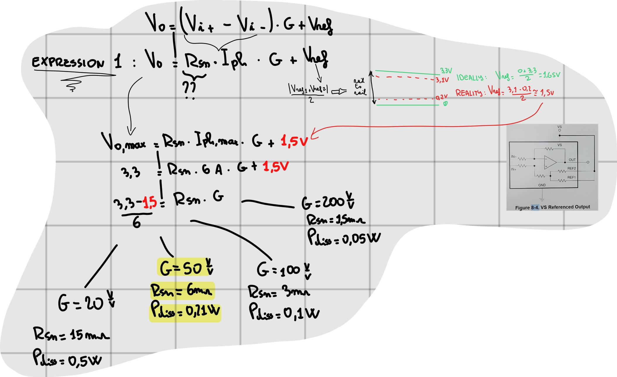
SmartSelect_20260511_112735_Samsung Notes.png

SmartSelect_20260511_112803_Samsung Notes.png

I've set G=50V/V and calculated Rsense=6m ohm

I would be grateful if you could provide some feedback on the calculations and the choice of 50V/V


  • Hello,

    The INA240 is a good choice for this application. There are slightly newer devices such as the INA241 and INA296 that also work well in motor drive applications that you may wish to look at to see if they are better fits for your particular requirements, but the INA240 is also made for this application and is a great part.

    Your calculations look good to me. The only thing I would like to point out to you is that the output of the INA240 does not swing all the way to supply, the swing is limited to within 50mV of the power rail, or 200mV of the power supply in the worst case. So if you need to sense 6A I would recommend reducing the shunt resistor slightly to 5mΩ.

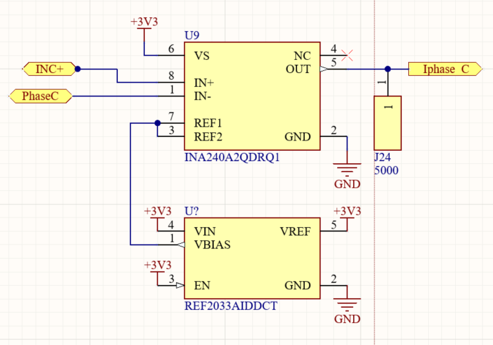
    The schematic snippet you posted does not use a 1.5V reference, and the INA240 is the 20V/V version. So you may need to update the part choice in the schematic.

    Let me know if you have any more questions,

    Levi DV

  • Hi, and thank you so much for your reply.

    You're right, I've just updated the main post with the correct INA240 schematic (I haven't updated the calculations, but never mind)

    I'm still not sure if is the RMS value sufficient for sizing, or do we also need the maximum/minimum and peak values since I'm using Field Oriented Control

    For a rectangular signal Ipk = Irms/D etc.

  • Hello,

    Using the peak values is the correct approach, but it looked like you already multiplied the RMS level by two, so I wasn't particularly worried about the difference between the RMS value and the peak since that should provide plenty of headroom. Or did you intend to double the FSR including the peak value?

    Levi DV

  • you are right! thanks

  • Hi, I’ve just realised that in the photo in the main post I used the REF5025 (which shouldn’t be suitable for my design as I’m using 3.3V).

    If I'm not wrong, then I should use the REF2033 .. but could you please confirm how it should be connected:

    I'm a bit confused about what I should connect to REF1 and REF2: Vin, Vref or Vbias?

    I should point out that I’m measuring the current on the motor phase, so it’s bidirectional

  • Hi Luca,

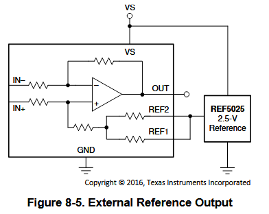
    The REF1 and REF2 pins are both part of a voltage divider that will average the zero current output voltage, so they are often shorted to the VS pin and GND pin of the INA240 itself for bidirectional operation:

    If you want to use an external reference to set the reference output to midsupply I would recommend shorting the ref pins to each other and connecting them to the reference voltage. For the REF2033, the VBIAS pin is the correct output since it will output a voltage that is half the supply voltage. I wouldn't recommend connecting the VREF pin to the 3.3V supply however, since that supply is already driven by another source.

    Let me know if you have any more questions,

    Levi DV

  • Thank you.

    So should I leave the Vref pin disconnected?

  • Hello,

    Leaving the Vref pin disconnected is one option, powering the INA240 directly from the VREF output of the INA240 (and disconnecting the 3.3V power supply from the INA240) will also work. Please note that the voltage reference device requires an input voltage slightly higher than 3.3V to operate:

    If your 3.3V line is a stable voltage level it is also possible that you can just use the built-in resistor divider and remove the voltage reference IC completely.

    I also noticed that you don't have any bypass capacitors in your schematic, it is the best practice to put a 0.1µA capacitor on the VS, VIN, VBIAS and VREF pins to GND in order to provide power supply filtering. 

    Let me know if you have any more questions,

    Levi DV

  • Hello, and thank you for your reply.

    Here is the diagram:

    (Vs already has 0.1uF in another part of the schematic)

    I’m not quite sure how to supply a voltage slightly higher than 3.3V for operation (excluding the option of a resistive divider). I have 3.3V coming out of the LDO.

  • I would recommend you ask a new question about the REF2033 then as I am not sure how a lower VIN voltage will affect the VBIAS level. The datasheet for the REF2033 indicates that a voltage slightly higher than 3.3V is required for operation. You could also try to use a different voltage reference that doesn't have this requirement, such as the REF30E.

    Levi DV