XTR111: XTR111 Damage

Part Number: XTR111
Other Parts Discussed in Thread: OPA2197

Hello,

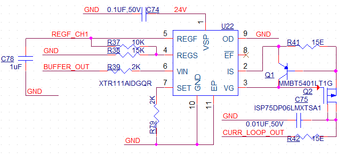
We are using XTR111 in a simple 4-20mA current loop application, with an extra loop protection using TPS26614 at its output. However, we have seen the XTR111 fail on multiple cards, and give out a limit current of 33-34mA even when there is no fault present at the output.

The circuit is shown here. The input voltage is in the range of 0-4V DC.

Can you please support us to resolve this? 

Regards

Gaurav


image.png

  • Hi Gaurav,

    Please help to answer the below questions to help clarify: 

    Do you have a failure rate or is there a trend of which XTR111 devices are current limiting? Has this application worked before and you are now seeing failures? Have you done an A-B-A swap to see if the failure follows the XTR111 device? 

    Where are you measuring the output current? At the output of the XTR (CURR_LOOP_OUT) or after the TPS26614? 

    Best regards,
    Ashley

  • Hi Ashley,

    1) We have seen 2 ICs fail in a total of around 60 nos.

    2) Yes, the application worked before.

    3) Swapping the failed IC of A with a good IC of B makes B to fail, and A starts to work.

    4) Whether we measure the current directly at the output of XTR111, or after the TPS26614 - in both cases the limit current of ~33mA is shown.

    Regards

    Gaurav

  • Hi Gaurav, 

    I'm a bit confused by your third statement of swapping a known good IC and then re-testing the failed unit. 

    3) Swapping the failed IC of A with a good IC of B makes B to fail, and A starts to work.

    Does unit A no longer exhibit the failure at all after replaced? Does it come back after operating for some time? Have you tested on multiple PCBs? 

    Do you have waveforms of the input and output? Could you share more of the input and output schematic, what the XTR111 is directly connected to? 

    Best regards,
    Ashley

  • Hi Ashley,

    Yes, the unit A no longer exhibits the failure, though we are still monitoring it for continuous operation. We did the same on both faulty PCBs and they work.

    The sch of the output is as shown below, it has a TPS26614 protection followed by TVS. Input comes from a voltage follower OPAMP stage.

    The waveform of XTR111 input (Pin 6 - Yellow) and TPS26614 output (Pin 5 - Blue) is shown below. Input in this case is a 80Hz, 200mV peak to peak signal with DC offset of 1.2V, output is terminated using a 100 ohm load. What we see at the output is a limiting current of ~33mA (3.3V). Pulsating is seen due to the TPS26614 auto-retry function.

    Regards

    Gaurav

  • Hello Gaurav, 

    Ashley is out of office on business travel so I will continue this thread support. 

    Could you please show what is connected to the other side of "BUFFER_OUT"? 

    For a 4-20mA application, I would expect to see a scaling input as such: 

    All the best,
    Carolina

  • Hello Carolina,

    Please see the input circuit below. The 4-20mA sensor input is sensed over a 200 Ohm res.

    Regards

    Gaurav

  • We are still awaiting an answer to our queries.

    Regards

    Gaurav

  • Hi Gaurav,

    Apologies for the delay.

    Caro and Ashley are currently out today but should be returning back to the office next week. 

    I've read through the E2E thread, and you said that part swap showed that the previous part that wasn't working now works and a known good part stops working. That leads me to think there's something else going on in the system. That behavior is what's really interesting to me. Have you tried swapping out any other parts on the board? 

    Best Regards,

    Robert Clifton 

  • Hello Gaurav, 

    Am I correct in assuming the voltage at PIN 3 of the OPA2197 is 0.8V (4mA) to 4V (20mA), as seen in the image below? 

    All the best,
    Carolina

  • I am sorry for the delay in response, my response never posted and the thread disappeared from the dashboard. 

    Thank you for the ping, please see my response above. 

    All the best,
    Carolina