Part Number: TAS5828MEVM
Hello,
I'm trying to use two TAS5828MEVM boards together to build a 4-channel active stereo setup (left/right tweeters and left/right woofers).
My aim is to connect both boards to the same I2C bus, with Board A acting as the controller and Board B as the target, so I can control both from a single instance of PurePath Console 3, with each board having its own I2C address.
So far, I have:
- Moved the J14 bridge to J18 and J15 to J16 in order to configure both amplifiers to be powered with an external 20 V DC PSU.
- Connected Board A to my PC via the micro-USB interface; this board is detected by PPC3 and works normally.
- Powered Board B from a separate 5 V USB charger and connected SDA, SCL, and GND between the two boards (via the TP20, TP19, and TP11 pins on each board).
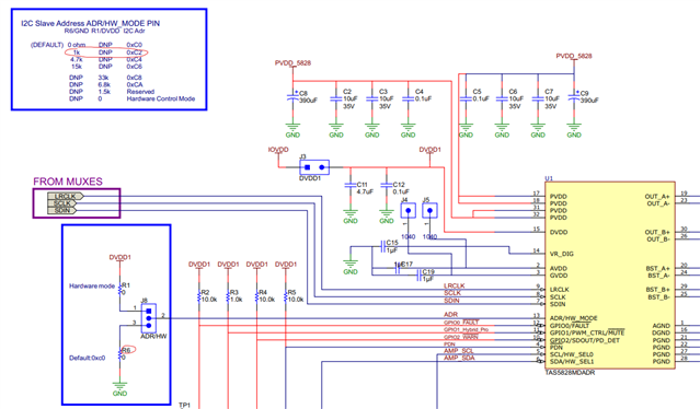
- Set Board B to HW address mode by moving J8 to the HW position.
- Added a 1 kOhm resistor from the ADR pin (centre pin of J8) to GND on Board B, which I understand should set the register address to 0xC2.
Board B powers up correctly, but when I try to select the custom configuration in PPC3, I get a message saying that it cannot be detected.
I also tried connecting both boards directly to the laptop via USB, but PPC3 then failed to detect either board.
Could you please confirm:
- Whether it is possible to use two TAS5828MEVM boards in this way with PPC3.
- Whether my address configuration for the second board is correct.
- Whether any other jumper settings need to be changed.
- How I can verify that the second board is responding on the I2C bus.
My end goal is to use two TAS5828MEVM boards as a 4-channel DSP amplifier platform for an active stereo speaker system.
Thanks very much for your help.
Best regards,
Sebastian