This thread has been locked.

If you have a related question, please click the "Ask a related question" button in the top right corner. The newly created question will be automatically linked to this question.

[FAQ] LOG200: Output oscillation

Part Number: LOG200

Hi All,


I have a question regarding the LOG200.

The output is oscillating on a customer's circuit board, and I am seeking your assistance.

The circuit board situation is as follows:
A PD in a completely dark state is connected to the I1 terminal.
It oscillates at approximately 500kHz when there is no input.
OUTB was disabled, but OUTA continued to oscillate.


I also confirmed the same phenomenon through simulation using PSpice.
The customer's circuit diagram is confidential information, so I would like to share the circuit diagram and simulation results via private message.

I believe the phase compensation in the datasheet circuit is insufficient.
Please tell me how to perform phase compensation for OUTA with this IC.


Best Regards,
Ishiwata

  • Hi Ishiwata-san, 

    Please share the schematic and simulation to me and I can review. Is the customer using the internal IBias to power the photodiode or providing the photodiode bias externally? 

    I will be on the lookout for your message. 

    Thank you!

    Best regards,
    Ashley

  • Hi Ishiwata-san, 

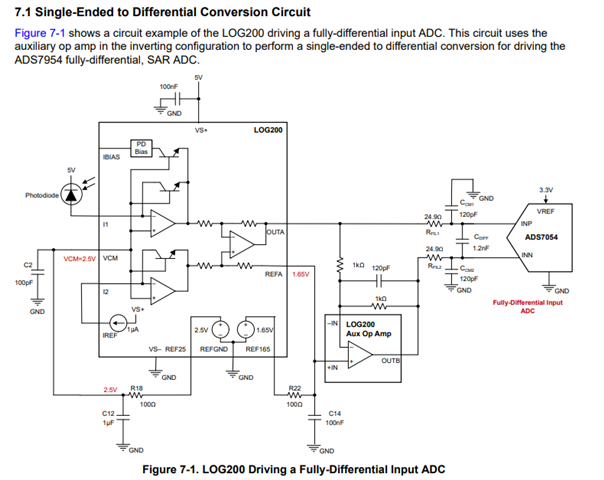
    Thank you for bringing this to our attention. The circuit diagram you were referencing for your design was Figure 1-1 in the App note and has an error in the diagram: 

    Perform Accurate Optical Current Sense Measurements Using the LOG200 Logarithmic Amplifier

    While we are in process of updating this document, please refer to Figure 7-1 for the correct configuration of the feedback capacitor. I have also attached a TINA simulation to help show the differences in behavior.  

    LOG200_auxamp_Cfb.TSC

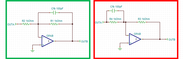
    To help visualize the difference, I have added the image below. Figure 1-1 Aux Amp is the red box and creates additional capacitance on the input that can cause stability issues. To limit the bandwidth of the aux amp, the feedback capacitor needs to be in parallel with the feedback resistor. 

    For more information on why this input capacitance causes stability issues, please see this TI Precision Labs video: http://ti.com/video/6341904813112

    For any boards that have the instable implementation, the following solutions can be implemented: 

    1. Depopulate the feedback capacitor - this should improve the stability of the op amp. 
    2. If a bandwidth limited capacitor is needed, a re-work of the board is required. Temporary solution to see if the capacitor is needed is to stack the capacitor on top of the feedback resistor so they are parallel to each other. 

    I will be making this thread a FAQ so other people can reference this but will also update once the App note changes have been published to TI.com. 

    Thank you!
    Best regards,
    Ashley