


Part Number: OPA2994
Other Parts Discussed in Thread: OPA994, OPA2810
I've used an OPA2994 as a buffer for a 2Vpp sinewave. One channel is just a straight non-inverting buffer, the other is wired as an inverter. The non-inverting buffer has no resistors, the inverting one has 470R input and feedback resistors. The chip is powered off +/-15VDC with 0.1µF MLCC's at the chip power pins.

The circuit is built on a bespoke PCB with short critical tracks. I bought the chips from Mouser along with a bunch of other parts. The bag says OPA2994IDR, the chip says OPA2994I, so all looks good. I have checked that the signal at the amplifier input is correct as coming from my signal generator. The output is just going to a Tek scope through a Tek scope probe. I found that both buffer outputs start rolling off at 1MHz, which surprised me. Below shows the buffer input in yellow and the two outputs in bue and red. The test frequency is 4MHz, which the amplifier should be able to easily do at unity gain.
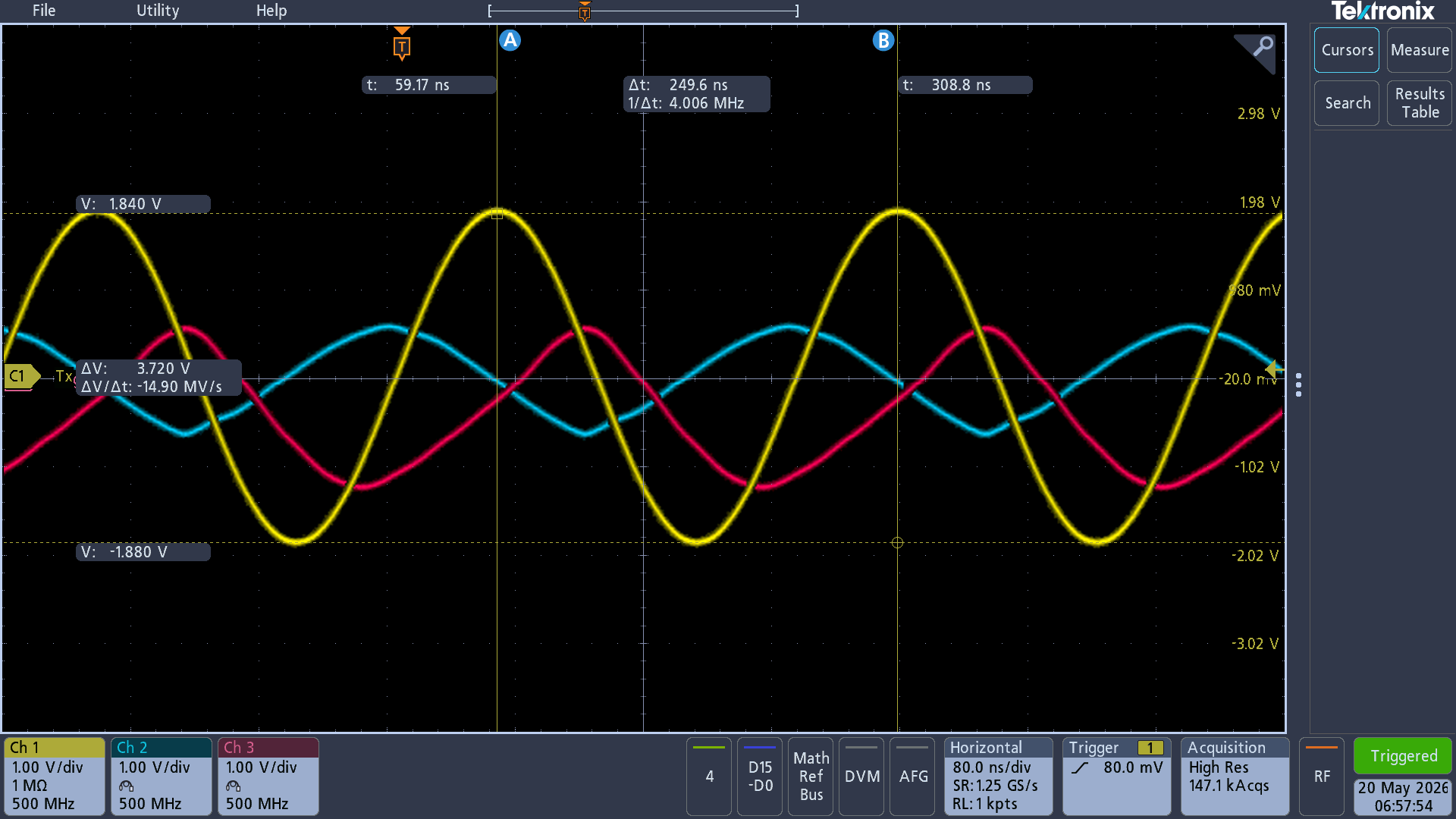
I did some tests on the opamp and found that the slew rate is 0.8V/µs whereas it should be 35V/µs. By applying a 500kHz square wave I found that the output would only get to about 0.5V of each power rail when it should get to within 20mV. I disconnected pin 3 from the input, so just running the inverting side in case the direct connection to pin 3 was the issue, but it made no difference to the performance of the inverting channel.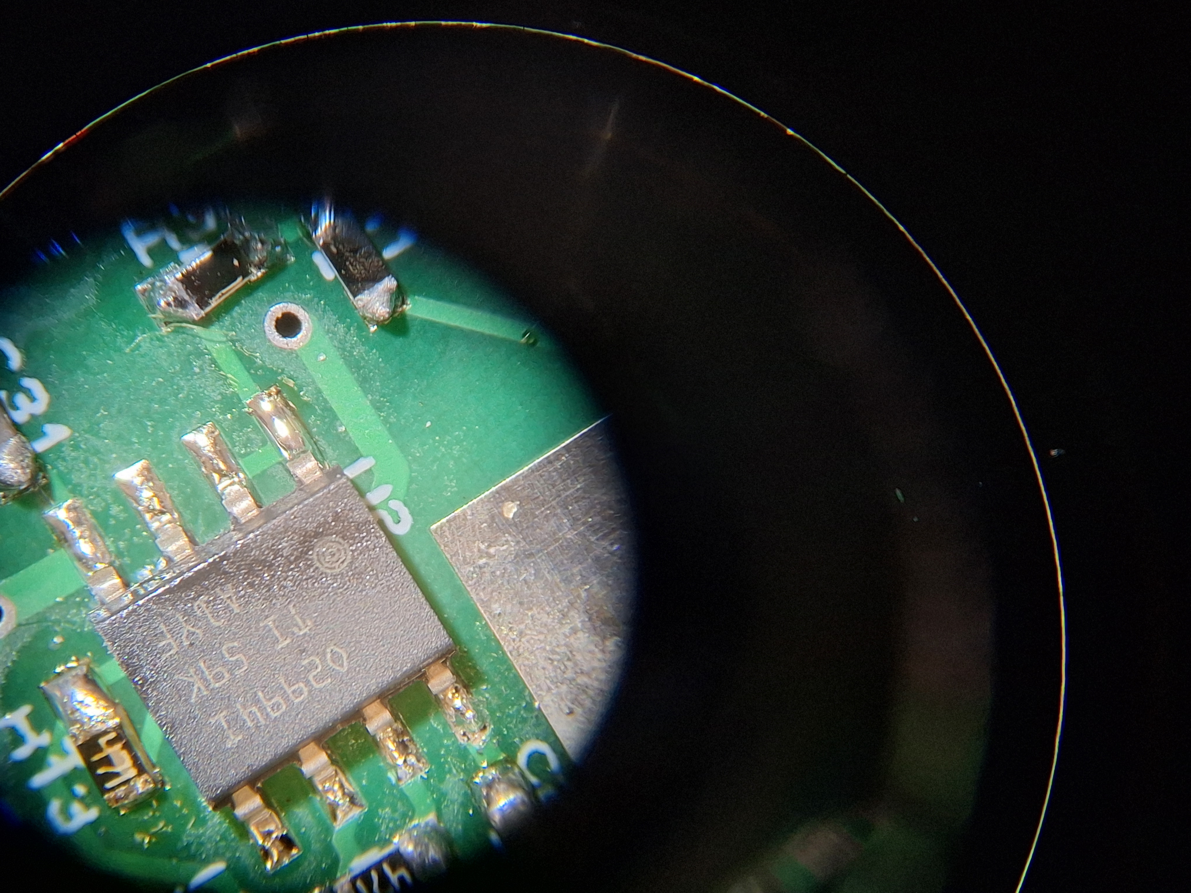
The performance I am measuring seems to match a 741! What am I doing wrong?
