


Part Number: THS4500
I am getting quite a bit of waveform distortion when using the THS4500 to convert a single ended signal to a differential signal for driving an ADC. I think this is due to my VCM being too low, but wanted to check this.
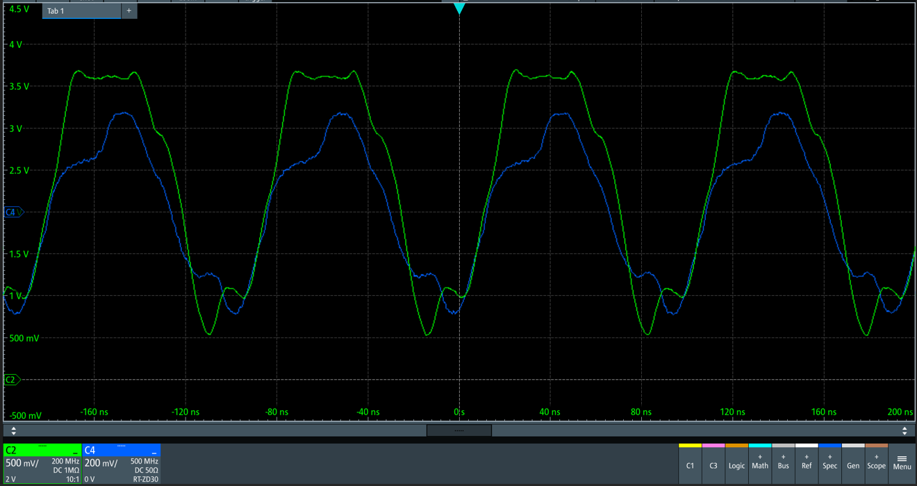
These are the sort of waveforms I am seeing. Green (CH 2) is the input waveform at 10MHz, blue (CH4) is the output waveform, measured with a differential probe.
My circuit is as follows. The THS4500 is operating from a single sided +5V supply. The inverting input is biased to 2.25V with a potential divider that has the same impedance as the input resistor on the non-inverting input.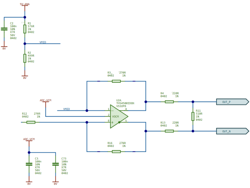
I am using the Common Mode output from my ADC to drive VCM. It looks like this can sufficiently drive to overcome the 25k input impedance, but it is only 0.9V. Looking at the datasheet I think the limit is 1V from the rails (i.e. between 1 and 4V). It looks like the individual output pins never drop below 1V when I probe them single ended (apart from some ringing), which I think stacks up with the datasheet quoted values of +-3.3V differential output swing with a common mode voltage of 2.5V.
Is my understanding on all this correct?

