INA196: Clarification Required on INA196AIDBVR Current Measurement Test Setup

Part Number: INA196

Hello TI Help Center,

We are using the INA196AIDBVR for current measurement in our design. For testing, we tried using a voltage-to-current module, and I have attached the relevant details of that module for reference.

However, we are unable to detect the expected current from this module using our circuit.

Could you please review whether this type of current module is suitable for testing our INA196AIDBVR-based current measurement circuit? If this type of module is not appropriate, kindly advise whether a different or special type of current source / loop device is required for proper testing.

If a different test module is recommended, please suggest a suitable type.
  https://rajivelectronics.com/productDetails/RB5V

  • Hello, 

    Thank you for your post. 

    As I understand, this module is being used in your control loop and you are using the INA196 to measure the output of this module. 

    Can you please provide a scope capture of the module output (INA196 input) and the INA196 output? 

    Please also provide the schematic and layout for the INA196 portion of the circuit for my review. 

    Best Regards, 

    Joe

  • Hello Joe,

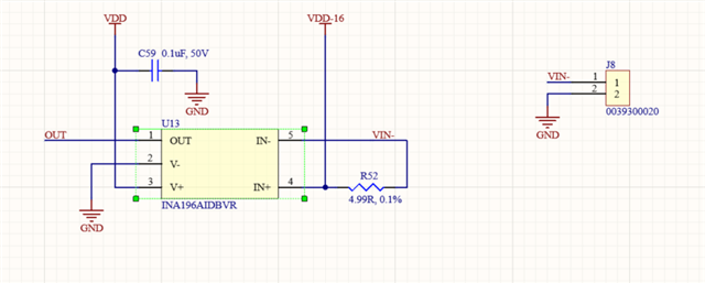
    Please find attached the schematic, PCB layout, and the folder containing the INA196 input and output waveforms for both conditions:

    • with the current module connected
    • without the current module connected

    Kindly review them and let us know your observations.

    Scope_Waveform.zip

  • Hello, 

    Thank you for providing this information.

    Based on the results, the IN+ and IN- input waveforms are violating the 18V maximum analog input ABS max conditions of the INA196.

    This will cause device damage. 

    When operating where the IN+ is above 20V and IN- is also 20V, the performance of the device is no longer valid and you can damage the INA196.

    Please correct your circuit to ensure that the recommended operating conditions are followed for the INA196.

    Depending on the load connected to J8 pins 1 and 2, can potentially try low side current sensing by changing the connections of your schematic like I am showing here:

    However, you may have damaged the device so I recommend replacing the unit with a new INA196.

    I hope this helps, 

    Joe

  • Hello Joe 
    please find attached updated schematic. 
    can you please once review it and let me know if you have any suggestions.
    ...

  • Chetan,
    Thanks for your patience. Due to the U.S. holiday, we are currently out of the office. Joe will reply when we return starting 5/26.

  • Hello Chetan, 

    Yes this is the proper way to implement low side current sensing. 

    I would still encourage you to measure the voltage on each side of the shunt before soldering the INA196 onto the board. 

    The recommended common mode voltage needs to be adhered to. 

    I hope this helps, 

    Joe

  • Hello Joe,

    Thank you for your help. Could you please explain the purpose of connecting 16V to the connector? Also, could you please advise how I can connect that module to this connector?