This thread has been locked.

If you have a related question, please click the "Ask a related question" button in the top right corner. The newly created question will be automatically linked to this question.

LM4811: Output noise issue

Part Number: LM4811

We are using the LM4811MM audio amplifier IC in our design. We are facing an issue where noticeable background noise is present in the audio output, and the actual audio is not clear enough to hear properly.

Could you please suggest possible reasons or solutions for reducing this background noise?
Are there any recommended PCB layout guidelines, filtering components, grounding methods, or gain settings that we should check?

here is the circuit design:
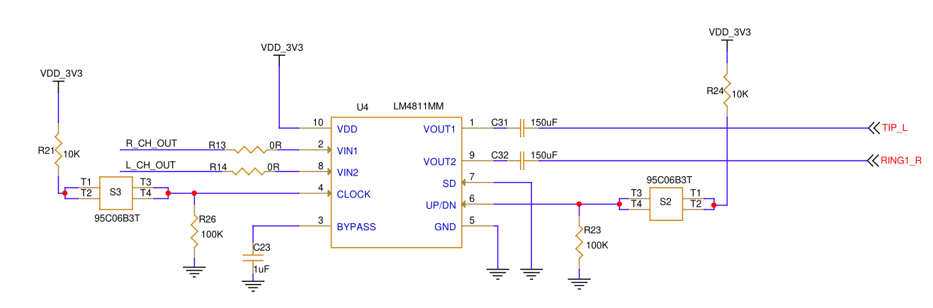
image.png

  • Hi,

    We will investigate this issue, review the schematics and provide feedbacks to you soon.

  • Hi,

    There are several critical points in the schematic that may be causing the noise. These should be prioritized:

    • Add Decoupling Capacitors (Critical Issue):

      • Problem:​ In the schematic, Pin 3 (BYPASS) is connected to ground only via C23 (1uF). For audio amplifiers, this capacitance is too small. A single 1uF ceramic capacitor cannot effectively filter out low-frequency power supply ripple or provide a stable internal bias voltage.

      • Suggestion:​ Add a 10uF to 47uF tantalum or electrolytic capacitor​ between Pin 3 (BYPASS) and ground. The existing 1uF ceramic capacitor can remain as a high-frequency decoupler in parallel with the larger cap. This will significantly reduce the hiss caused by power supply ripple.

    • Input DC Isolation:

      • Problem:​ L_CH_OUT and R_CH_OUT are connected directly to VIN1 and VIN2 via analog switches, with only 0-ohm resistors (R13, R14) in series. There are no obvious DC-blocking capacitors. If the preceding audio source has a DC offset, it will shift the amplifier's operating point, causing "popping" sounds or distortion.

      • Suggestion:​ Verify the DC bias of the pre-stage output. If the pre-stage is AC-coupled, consider adding DC-blocking capacitors (e.g., 4.7uF or 10uF) before VIN1/VIN2.

    • Power Supply Decoupling:

      • Suggestion:​ Add a 0.1uF ceramic capacitor near the VDDpin (Pin 10) to ground to filter out high-frequency interference.

  • Regarding Layout guidelines, as Background noise is often related to ground loops and electromagnetic interference (EMI). Pleaser refer to below instructions.

    • Minimize Trace Length:

      • Input signal traces (VIN1/VIN2) should be as short as possible​ and kept away from power lines (VDD_3V3) and clock lines. Long traces act as antennas, picking up high-frequency interference.

      • Output traces (VOUT1/VOUT2) carry significant current; use wider traces to reduce impedance.

    • Bypass Capacitor Ground Path:

      • The ground terminal of the decoupling capacitor on Pin 3 (BYPASS) should connect directly to the chip's GND pins (Pin 5)​ to form the smallest possible current loop. Do not route it through long ground traces.

  • Regarding grounding methods, since LM4811 handles analog audio and is highly susceptible to digital noise. It is recommended to connect all audio-related grounds to a single point before connecting to the system ground. 

  • It is recommended to test in the following order:

    1. Disconnect Inputs:​ Temporarily disconnect R_CH_OUT and L_CH_OUT(or unplug the headphone jack) and power up the chip only. If you still hear obvious "hissing" (white noise), the issue is power supply or inherent chip noise. Focus on decoupling caps and grounding.

    2. Measure Voltage:​ Use a multimeter to measure the voltage at Pin 3 (BYPASS) relative to ground. Normally, it should be VDD/2(approx. 1.65V). Abnormal voltage indicates failed decoupling or a damaged chip.

    3. Substitution Test:​ If possible, try feeding a known clean audio source (like an MP3 player) with a pure sine wave or music signal into the amplifier to rule out the possibility that the pre-stage source itself is noisy.