This thread has been locked.

If you have a related question, please click the "Ask a related question" button in the top right corner. The newly created question will be automatically linked to this question.

LM2903B: LM2903 comparator doesn't work correctly

Part Number: LM2903B
Other Parts Discussed in Thread: LM2903, LM393LV

Hello,

I am writing you regarding a circuit that I am designing using the comparator LM2903B. The circuit should sense the existance of the negative voltage rail of -5V5.

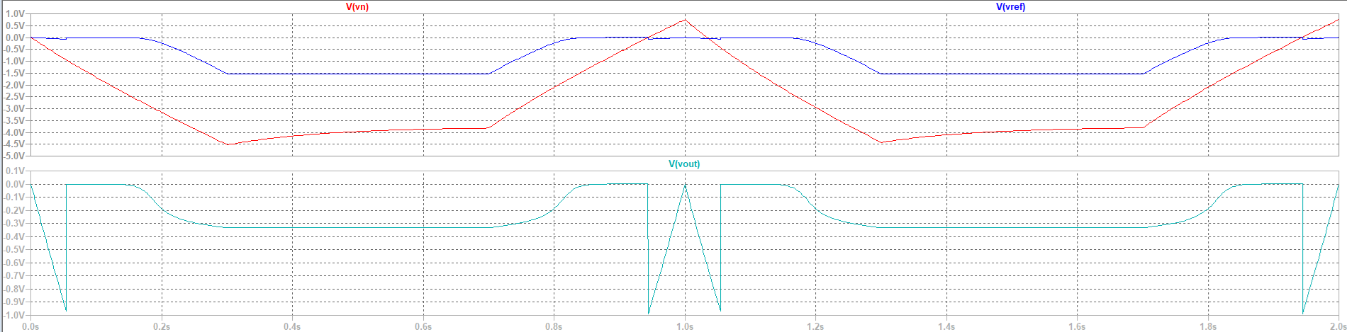
Both voltages present at the "+" and "-" terminals of LM2903 are inside of the common mode votlage range. As it can be seen from the waveforms plot, the output voltage seems to not be stable.

Could you help me please to undersand what is wrong in my circuit?

Thank you in advance!
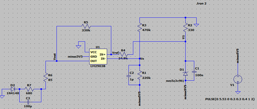
LM2903B_circuit.pngLM2903B_circuit_waveforms.png

  • LTSpice is not supported by TI.

    It is a common error in various SPICE models that they assume that the GND pin is connected to 0 V. Try changing your power rails to 0 V and +5.5 V; if this helps, then the problem is with the model and not with your circuit.

  • Hi Clemens,

    Thank you very much for your feedback.

    I did the change that you suggested and it seems to work.

    Could you tell me please, if you know what changes have to be implemented in the spice model in order to make it working also for my application?

    Thank you,

    Best regards,

    Marius

  • Marius,

    The models below work with VCC at ground and GND powered with negative voltages. 

  • Hi Ron,

    Thank you very much for the models. 

    Please see below the LTSpice simulation circuit updated with Rev E of LM2903 Pspice Model, and the voltage waveforms of the both inputs and output.

    In my opinion Vout should swing between -332mV and -5V5+250mV=-5.25V. 

    Could you help me please to understand why Vout is switching between 0V and -332mV?


    Best regards,

    Marius

  • Marius,

    Vout is -0.3V (open collector  because IN+ > IN-; -1.5V > -4V)  

    Vout is 0V (off) because -5.5V supply is 0V

    At no time is IN+ < IN-

  • Hi Ron,

    Thank you very much for your answer.

    I did a small change in my circuit, I changed the values of R1 and R3. R1- > 470K and R3-> 220K.

    Now there are periods of time when IN- will be higher than IN+. It can be seen that the Vout drops from -333mV down to -3.88V, but for a very short period of time because it is synchronized with the pulse shape of the power supply.


    Best regards,

    Marius

  • Hi,

    I did few changes to the circuit:

    - I changed the zener diode to one that has a lower Vbr, like 2.4V

    - I updated the values of resistors R2 (330 -> 620 Ohms) and R1( 470k- > 330k)

    The inputs of the comparator are now inside of the CMVR: IN- : -2.2V and IN+: -2.938V

    I think that the circuit works fine now. What do you think?


    Best regadrs,

    Marius

  • Marius,

    This looks much better. 

  • Hi Ron,

    Thank you very much.

    During this time, since I have started this thread, I tried different alternatives for the comparator input voltages for making it to work, and I observed that there could be improvements in the output voltage waveform shape also when one of the inputs or both inputs are outside of the common mode voltage range.

    I know that according to the theory the inputs shall be inside of the CMVR, because in this case the comparator works in a controlled way, and the data from the datasheet applies.

    Therefore, could you tell me please, how important is to have the inputs inside of the CMVR? And in which case it can be avoided?

    Thank you,

  • Marius,

    At least one of the inputs needs to be correct otherwise the comparator can't respond to inputs. Cover one of your eyes and you can see, cover both and you can't see. 

    For low voltage circuits, there is LM393LV that has rail to rail input. Much easier to use.