TLC372: Step 25 – RESYNC Testing & Step 26 – Rotor Signal Testing - TLC372CPWR - Failure

Part Number: TLC372

Hello Team , 

Can you check and advise the possible rootcauses for below issue and validate in tehnical way? 

Station & Steps: FCT station; failing during Step 25 (RESYNC Testing) and Step 26 (Rotor Signal Testing).

Affected Variants: US6X and HV6X.

Root Cause: A defective U3 comparator IC on the Control Board.

Verification: Confirmed by cross-swapping U3 with a known good board (the failure followed the component) and validating with abnormal diode-mode readings.
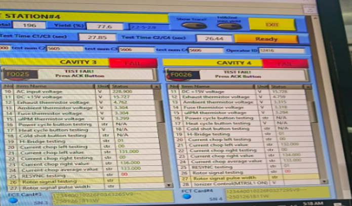
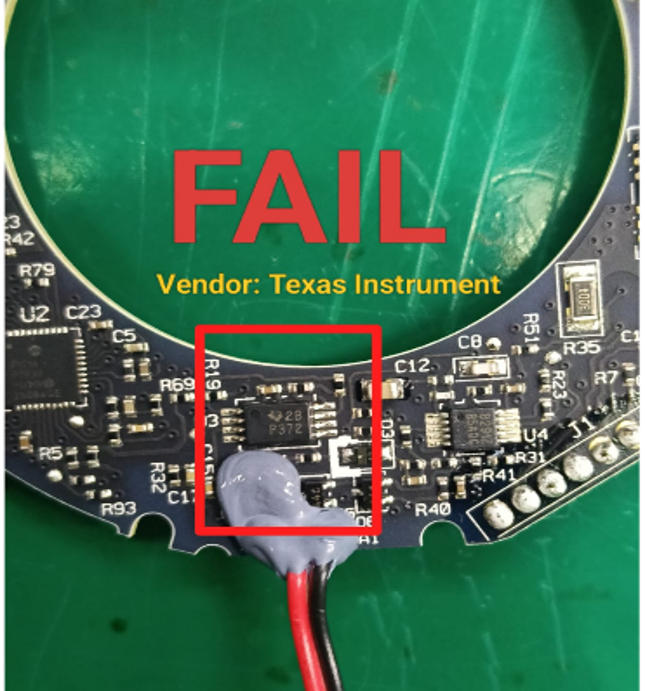
 

image.png

image.png


Looking forward for your support and advise steps to rectify this issue and what need to be checked to solve this issue.

Thank you. 


  • Hello Manoj,

    TLC372CPWR has a PCN that changes design and process that will affect in circuit testing "diode" curves. This is not a failure; it is a change

    https://www.mouser.com/PCN/Texas_Instruments_PCN20240202009.1_Change_Notification.pdf

    Can you show waveforms for inputs and output?

  • Hello Ron , 

    Thanks for your reply and sharing the supporting document. 

    Here the most of the components are passing with parameters, In specific to this PCN any changes we need to taken care at design level and need your technical advise. Addition to that these parts are used in HVAC controls only failed at ROTOR signal processing at 24th and 25th STEP of testing. Can you please advice on input and output side supply of the component. Below the findings 

    Investigation: 

    Verified the FCT tester and fixture condition.

    Confirmed the failure was repeatable on the affected PCBA.

    Inspected the PCB for visible defects, solder abnormalities, damaged traces, and missing components.

    The supply voltage to the U3 comparator IC was measured during FCT and confirmed to be within the expected operating specification. The same 5 V supply rail is also utilized by the H-Bridge circuit (Step 19), which passed without any abnormalities. This confirms that the 5 V supply was stable throughout testing and eliminates power supply instability as the root cause of the U3 failure.

    Performed component cross-swap verification using the U3 comparator (TLC372CPWR) between a failed board and a known good board. 

    Findings 

    No abnormality was observed on the PCB assembly.

    U3 supply voltage remained stable during testing.

    The FCT fixture and test program were verified to be functioning correctly. Cross-swap testing demonstrated that the failure migrated together with the U3 comparator IC.

    No internal fixture or evaluation board is available to perform standalone electrical or functional verification of the TLC372 comparator IC.

    Looking forward for your technical insights on this. 

  • Manoj,

    5V supply is good. What are the inputs and output?